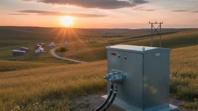
A Switchgear Panel is the control point where electrical power is received, measured, protected, and distributed. It may look like a row of steel cabinets, but each compartment has a defined purpose. Inside, busbars carry current, circuit breakers interrupt faults, and protection relays monitor abnormal conditions. Current transformers and voltage transformers provide measurement signals for reliable protection. The equipment works as a coordinated system, not as a collection of isolated parts.
The International Energy Agency’s Electricity 2024 report expects global electricity demand to grow by about 4% annually through 2026. More demand places greater pressure on distribution networks, industrial facilities, and data centers. A properly selected panel can isolate a short circuit within milliseconds, limiting damage and reducing service disruption. IEC 62271-200 provides requirements for many medium-voltage metal-enclosed switchgear assemblies, while IEC 61439 addresses low-voltage assemblies. These standards support consistent design, testing, and verification.
Still, a standard cannot replace engineering judgment. A neat schematic is not the whole truth. Cable heat, moisture, dust, and poor maintenance can change real performance. During inspection, technicians may hear a faint hum, see a warm connection on thermal imaging, or find a breaker indicator in the wrong position. Those details matter. This guide explains what a Switchgear Panel contains, how power flows through it, and how protective devices respond to faults. It also considers ratings, interlocking, maintenance, and safety practices. Work must follow the manufacturer’s instructions, applicable electrical codes, and qualified-person procedures. Mistakes are possible, so every design deserves a careful review before energization.
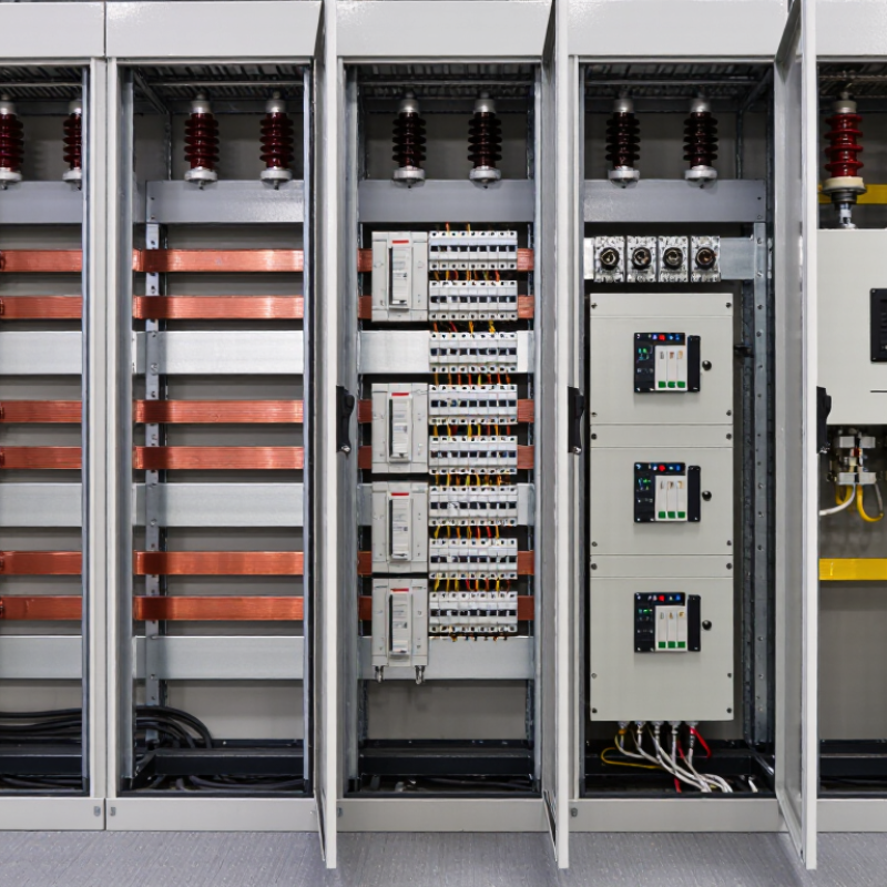
A switchgear panel is an enclosed electrical assembly that controls, protects, and isolates power circuits. It may contain circuit breakers, disconnect switches, busbars, protective relays, meters, and control wiring. These parts work together inside a grounded metal cabinet. Think of it as a traffic controller for electricity. It directs power toward equipment while limiting damage during abnormal conditions.
Under normal operation, current enters through an incoming connection and travels along the busbar. Feeders then carry power to motors, transformers, or distribution boards. When a fault creates excessive current, a protective relay detects the condition and signals the circuit breaker to open. The breaker separates its contacts quickly, interrupting the circuit. A visible position indicator helps technicians confirm whether the circuit is open, closed, or grounded.
In field inspections, technicians check cable terminations, insulation condition, torque markings, and signs of heat near the busbar. Moisture and dust can weaken insulation, even when the panel appears clean. Interlocks also prevent unsafe switching sequences, but they should never replace approved operating procedures. Specifications must match voltage, fault current, enclosure rating, and installation conditions. A simplified explanation can hide important differences between low-voltage and medium-voltage equipment. That is where careful engineering matters. Even a small wiring error may cause false trips, delayed protection, or difficult maintenance.
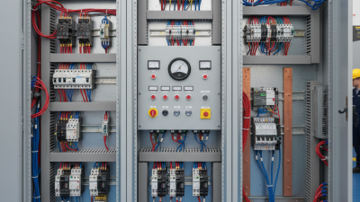
A switchgear panel is a controlled enclosure that manages electrical power safely. Its main components work together to distribute energy, isolate faults, and protect connected equipment. The metal enclosure provides mechanical protection and helps prevent accidental contact with live parts. Inside, copper or aluminum busbars carry current between incoming and outgoing circuits. Their spacing, insulation, and temperature ratings require careful engineering.
Circuit breakers or fuses interrupt current when overloads or short circuits occur. A breaker can usually be reset, while a fuse must be replaced after operation. Disconnectors create a visible isolation point during maintenance, but they should not replace proper safety procedures. Current transformers and voltage transformers reduce electrical values for meters and protection relays. These devices help operators monitor load conditions without exposing instruments to full system voltage.
Protection relays analyze signals from the transformers and command breakers to open when abnormal conditions appear. Control wiring connects relays, switches, alarms, and remote monitoring equipment. Grounding bars provide a planned path for fault current and support safer operation. Metering devices display voltage, current, power, and energy use. Small details matter.
In field inspections, loose terminals, incorrect labels, and blocked ventilation are common weaknesses. A panel may meet its design standard yet perform poorly after rushed installation or neglected maintenance. Technicians should verify torque settings, insulation condition, clearances, and breaker operation against approved drawings. Human error remains a practical concern. Safety interlocks and clear documentation reduce that risk.
A switchgear panel controls, protects, and isolates electrical circuits inside a metal enclosure. It usually contains circuit breakers, busbars, relays, meters, and grounding equipment. Power enters through an incoming feeder and reaches the busbars. The busbars distribute electricity to outgoing circuits. This arrangement keeps high-current paths organized and easier to inspect.
When a fault occurs, protective relays detect unusual current, voltage, or leakage. They send a trip signal to the circuit breaker. The breaker then opens its contacts and interrupts the fault current. Fast action can reduce equipment damage and lower fire risks. During normal operation, operators can close or open breakers to manage connected loads. Mechanical and electrical interlocks help prevent unsafe switching sequences.
Safety depends on more than the panel itself. Technicians verify ratings, cable connections, insulation condition, and grounding before energizing equipment. They may use thermal imaging to find loose terminals that feel normal but run dangerously hot. A visible position indicator helps confirm whether a breaker is open or closed. Some panels include an arc-resistant design, although protection is never absolute. No inspection plan is perfect. Dust, moisture, aging insulation, or an overlooked connection can still create trouble. Regular testing should follow the installation’s voltage level, environment, and maintenance requirements. Personnel must also follow approved isolation and verification procedures before opening the enclosure.
What Types of Switchgear Panels Are Used?
Switchgear panels differ by voltage level, insulation method, installation location, and maintenance needs. Low-voltage panels commonly serve commercial buildings, factories, and distribution boards. They protect circuits below 1,000 volts using breakers, fuses, meters, and control devices. Medium-voltage panels support larger facilities and utility networks. Their compartments usually separate busbars, incoming feeders, and outgoing circuits.
Air-insulated switchgear uses air around energized conductors. It is familiar, accessible, and often easier to inspect. Gas-insulated switchgear uses sealed insulation, so it needs less floor space. This design suits compact substations, although technicians require specialized training and strict leak-control procedures. Some projects also use solid-insulated systems, especially where environmental conditions or space restrictions matter.
Fixed panels hold switching devices permanently in place. Draw-out panels allow breakers to move between connected, test, and isolated positions. That feature can reduce service time and improve worker safety during maintenance. Indoor panels protect equipment from weather, while outdoor enclosures resist rain, dust, sunlight, and temperature changes. In field inspections, small details matter: loose terminations create heat, blocked ventilation raises temperature, and unclear labels slow emergency response. Classification is not always neat. A panel may combine several designs. Engineers must match the panel to fault levels, load growth, coordination studies, enclosure ratings, and local electrical codes. A low-cost choice can become an expensive maintenance problem.
Operating a switchgear panel begins with a controlled sequence, not a hurried turn of a handle. Authorized technicians review drawings, load conditions, protection settings, and inspection records. They wear suitable PPE and confirm isolation boundaries before opening any compartment. A status indicator is useful, but it does not prove zero energy. Technicians verify the absence of voltage with a properly rated tester, then apply locks and tags. Keep the area dry and clear. Small mistakes can become severe faults.
During normal service, operators monitor current, voltage, temperature, alarms, and unusual sounds. A warm smell, cracked insulator, or buzzing enclosure deserves immediate attention. Remote controls can reduce exposure, yet they still require local confirmation and clear communication. When switching feeders, use an approved operating order and pause after each position change. Never defeat an interlock to save time. That shortcut may hide a mechanical or electrical problem. Work logs should record readings, trips, environmental conditions, and corrective actions.
Maintenance intervals depend on duty, contamination, humidity, and fault history. Qualified personnel inspect bus connections, insulation, grounding paths, mechanisms, shutters, and protective relays. Cleaning methods must suit the equipment; compressed air can spread dust into sensitive areas. Torque checks require calibrated tools and approved specifications. Functional tests should confirm trip circuits, alarms, interlocks, and breaker timing. “Looks fine” is a weak maintenance result. Photographing defects and scheduling follow-up work creates stronger evidence. An independent review is worthwhile when readings change unexpectedly.