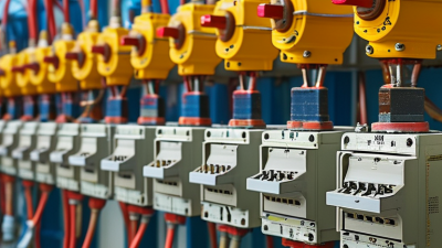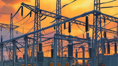
Choosing the right Solar Power Substation in 2026 requires more than comparing voltage ratings or equipment prices. Developers must examine the entire project environment. This includes solar capacity, grid strength, land conditions, weather exposure, maintenance access, and future expansion plans. A substation beside a dusty desert array faces different risks from one near a humid coastline. Salt corrosion, heat, flooding, and unstable soil can quietly increase lifetime costs.
Dr. Fatih Birol, Executive Director of the International Energy Agency, has stated, “There is no clean energy transition without electricity grids.” His observation highlights the substation’s central role. It connects solar generation with reliable transmission and distribution systems. A suitable design should include correctly rated transformers, protection relays, switchgear, monitoring systems, and safe isolation equipment. It should also support grid-code compliance and practical fault management.
The cheapest option may not be the most reliable. That lesson is easy to overlook. An experienced project team should compare lifecycle cost, not only the purchase price. It should request tested performance data, verified references, and clear service commitments from suppliers. Engineers should also assess spare-part availability and response times before signing a contract.
There is no universal substation design. Every site changes the decision. Some early assumptions may prove wrong after soil surveys or grid studies. Therefore, this guide examines the technical, financial, operational, and environmental factors that shape a sound choice. The goal is not simply to install equipment. It is to build a dependable energy connection for decades.
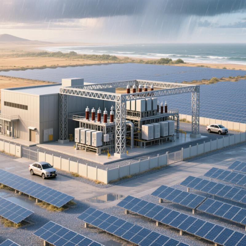
A solar power substation connects the photovoltaic plant to the wider electricity network. It collects power from multiple inverter units and raises the voltage through transformers. This voltage increase reduces transmission losses across long distances. The substation also manages switching, protection, measurement, and controlled power delivery.
Its core functions depend on reliable equipment and accurate system design. Protection relays detect faults and isolate damaged sections quickly. Circuit breakers interrupt abnormal currents before equipment suffers serious harm. Metering systems track energy output, voltage, frequency, and power quality. Supervisory controls help operators observe changing conditions from a control room.
Site conditions should guide the selection process. Dust, heat, salt air, flooding, and limited access can affect service life. A practical design includes drainage, ventilation, fire protection, grounding, and safe maintenance space. Engineers should check transformer capacity against present output and future expansion. Oversizing feels safe, but it can increase cost and reduce efficiency.
Field experience often reveals small weaknesses. A poorly placed cable trench may collect water after one storm. A narrow service path can delay repairs. These details deserve review before construction. Compliance with grid codes and electrical standards is essential. Independent testing, documented commissioning, and periodic inspections improve confidence in long-term operation. Yet no design is perfect; weather data and production forecasts can still be wrong.

Choosing a solar power substation in 2026 starts with the site, not the equipment catalog. According to IRENA’s Renewable Capacity Statistics 2024, solar power added about 346 GW globally in 2023. That scale hides major differences between projects. A dry desert site may deliver strong irradiance but create severe dust, heat, and cooling challenges. Coastal sites demand stronger corrosion protection. Flood-prone land requires elevated equipment and carefully designed drainage.
Measure more than annual sunlight. Record hourly irradiance, ambient temperature, wind, humidity, soil resistivity, seismic conditions, and elevation. High temperatures reduce transformer and inverter capacity. Dust can increase cleaning costs and reduce generation. Weak soil resistivity can raise grounding complexity. A failed assumption here becomes an expensive change order. The spreadsheet may still lie.
Plant requirements define the substation architecture. Confirm the inverter output voltage, collector voltage, export limit, reactive-power range, harmonic performance, and grid fault requirements. Size transformers for expected loading, temperature derating, and future expansion. The IEA’s Renewables 2024 report states that solar represented roughly three-quarters of global renewable capacity additions in 2023. Grid queues are therefore becoming more crowded, making protection studies and interconnection data especially important.
Use measured site data whenever possible. Short campaigns can miss seasonal extremes, so satellite records should be cross-checked with on-site sensors. It is not perfect. That uncertainty deserves a contingency allowance. A practical design also leaves safe maintenance access, spare feeder capacity, fire separation, and room for replacement equipment. A compact substation is not always an efficient one.
How to Choose the Right Solar Power Substation in 2026?
Choosing a solar power substation begins with voltage, not appearances. A utility-scale project may collect energy at medium voltage, then export it at a higher grid voltage. The correct level depends on the interconnection point, distance, and utility requirements. Higher voltage can reduce transmission losses, but it also increases insulation, clearance, and protection demands. I have seen projects underestimate cable distances and later face costly redesigns.
Capacity must match the solar plant’s real operating profile. Compare inverter output, transformer rating, expected overloads, and future expansion plans. A transformer sized only for today may restrict tomorrow’s generation. However, excessive oversizing can increase idle losses and capital costs. Review peak output, ambient temperature, altitude, and cooling conditions. A dusty site may need more careful thermal planning. Small details matter.
Grid compatibility requires more than matching voltage and frequency. Engineers should verify phase sequence, grounding, short-circuit levels, reactive power control, harmonics, protection coordination, and communication interfaces. Anti-islanding functions must align with local grid rules. The substation should also support reliable monitoring during faults and maintenance. Utility studies and certified design reviews provide stronger evidence than a supplier’s brochure. Even experienced teams can miss a protection setting when project schedules become tight. That risk deserves an independent check.
Comparing substation voltage, capacity, and grid compatibility
Higher-voltage substations generally support larger solar plants and longer-distance grid connections with lower transmission losses. The 33 kV and 66 kV classes are commonly associated with distribution or sub-transmission interconnections, while 110 kV and 132 kV are more suitable for larger projects requiring stronger transmission-level grid access.
The capacity figures are representative utility-scale planning values rather than fixed limits. Actual grid compatibility depends on available hosting capacity, fault level, protection coordination, voltage limits, reactive-power capability, and the requirements of the local grid operator.
How to Choose the Right Solar Power Substation in 2026?
Solar capacity is expanding faster than many substation designs were built to handle. IRENA reported 585 GW of renewable capacity additions in 2024, with global solar capacity reaching about 1,865 GW. That scale makes protection and automation practical priorities, not brochure features. Choose relays that detect ground faults, overcurrent, islanding, and abnormal voltage quickly. IEC 61850 communication can reduce wiring and improve event visibility. However, digital protection is only reliable when settings are tested under realistic fault conditions.
Safety begins with physical details. Specify visible isolation points, interlocks, arc-flash controls, clear labels, and safe maintenance access. The International Energy Agency expects renewable capacity to increase by almost 5,500 GW between 2024 and 2030. More assets mean more switching operations, inspections, and human exposure. A substation should therefore support remote operation, thermal monitoring, and recorded disturbance analysis. Small design gaps become expensive later.
Reliability needs evidence, not confidence. Ask for factory test records, protection coordination studies, battery autonomy calculations, and documented commissioning procedures. Review transformer temperature limits, surge protection, spare-part access, and network redundancy. NERC reliability assessments continue to identify inverter-based resources as an area requiring stronger modeling and grid coordination. The uncomfortable point is simple: a sophisticated system can still fail after one incorrect setting. Require independent verification, but keep questioning your assumptions.
Technical screening matrix for utility-scale and commercial solar photovoltaic substations
| Evaluation area | Key decision metric | Recommended 2026 screening benchmark | What to verify before purchase | Priority weight | Risk if below benchmark |
|---|---|---|---|---|---|
| Grid compatibility | Interconnection voltage and fault level | Match the approved grid voltage, frequency, grounding method, short-circuit duty, and utility interconnection study. | Utility requirements, load-flow study, short-circuit study, grounding study, and equipment ratings. | 20% | Rejected interconnection, nuisance trips, equipment damage, or delayed energization. |
| Protection coordination | Selectivity, sensitivity, and clearing time | Protection settings must coordinate from inverter collector circuits through the step-up transformer and point of interconnection, with documented time-current curves. | Protection coordination study, relay setting files, trip-circuit supervision, and end-to-end testing plan. | 18% | Unnecessary plant trips, failure to clear faults, thermal damage, or wider grid disturbances. |
| Relay functions | Coverage of AC, transformer, bus, and interconnection faults | Include overcurrent, earth fault, over/undervoltage, over/underfrequency, differential protection where applicable, breaker failure, and anti-islanding functions. | Protection philosophy, one-line diagrams, relay function list, inverter fault-current characteristics, and utility settings. | 15% | Blind protection zones, delayed fault clearing, unsafe islanding, or non-compliance with grid-code requirements. |
| Automation and control | Remote control, interlocking, and sequence reliability | Provide local/remote control, electrical interlocks, synch-check, breaker failure logic, event recording, and fail-safe operation during communication loss. | Functional design specification, cause-and-effect matrix, control logic tests, and loss-of-communications test results. | 12% | Incorrect switching, extended outages, unsafe restoration, or loss of operating visibility. |
| Digital communications | Interoperability and time synchronization | Prefer standards-based substation communication using IEC 61850 where specified, with redundant network paths and time synchronization suitable for sequence-of-events records. | Communication architecture, protocol list, network redundancy, cybersecurity zones, time-source design, and interoperability test reports. | 10% | Lost alarms, inaccurate fault analysis, communication-induced trips, or difficult future expansion. |
| Transformer performance | Thermal capacity, impedance, losses, and insulation | Select continuous and emergency ratings from the load-flow study; verify impedance, vector group, insulation level, temperature rise, cooling class, and tap requirements. | Routine and type-test documentation, guaranteed losses, temperature-rise results, oil or dry-type inspection records, and tap-changer requirements. | 10% | Reduced energy yield, overheating, insulation aging, or transformer failure. |
| Arc-flash and personnel safety | Incident energy and safe access | Complete an arc-flash assessment, use arc-resistant or remote-operation measures where justified, and provide visible isolation, grounding points, barriers, and safe approach distances. | Arc-flash study, equipment labels, interlock tests, access-control plan, grounding design, and applicable electrical safety procedures. | 10% | Severe injury risk, unsafe maintenance, regulatory non-compliance, or restricted operation. |
| Surge and lightning protection | Impulse withstand and surge protection coordination | Coordinate surge arresters, shielding, bonding, and grounding with the insulation-coordination study and site lightning exposure. | Lightning-risk assessment, arrester energy rating, insulation levels, grounding measurements, and inspection access. | 5% | Insulation flashover, inverter damage, control-system failures, or repeated outages. |
| Environmental suitability | Temperature, humidity, dust, altitude, and corrosion | Specify enclosures, creepage distances, cooling, coatings, and derating for the actual site climate, altitude, pollution level, and flood exposure. | Site environmental data, enclosure rating, corrosion category, altitude derating, HVAC calculations, and flood-elevation design. | 5% | Premature corrosion, overheating, insulation tracking, water ingress, or reduced service life. |
| Reliability and maintainability | Availability, spare strategy, and mean time to repair | Require maintainable layouts, condition monitoring, accessible test points, critical spares, documented maintenance intervals, and a lifecycle support plan. | Reliability model, preventive-maintenance schedule, spare-parts list, diagnostic functions, training plan, and warranty terms. | 5% | Longer outages, higher operating costs, difficult troubleshooting, and lower plant availability. |
Choosing a solar power substation starts with the site, not a product catalog. Confirm the plant’s voltage, capacity, terrain, temperature range, and grid connection requirements. Equipment should include suitable transformers, switchgear, protection relays, metering, grounding, and communication systems. Dusty sites need sealed enclosures and accessible filters. Coastal projects require stronger corrosion protection. Small details matter.
Budget for the entire operating life, not only the purchase price. A cheaper transformer may consume more energy or require expensive repairs. Request documented efficiency data, factory testing records, warranties, and service response times. Include civil works, transport, installation, testing, spare parts, and technician training. In project reviews, hidden site costs often cause the biggest budget errors. My own preference is a clear cost schedule, although estimates still change after geotechnical testing.
Maintenance access should influence the layout. Leave safe working space around transformers and switchgear. Use monitoring for temperature, partial discharge, oil condition, and protection alarms where practical. Keep inspection logs with dates, readings, and corrective actions. Plan thermal imaging and relay testing at defined intervals. Do not ignore simple checks. A loose connection can become a long outage.
Future expansion needs deliberate space and electrical capacity. Reserve cable trenches, spare feeder positions, control-system inputs, and land for additional transformers or battery storage. Oversizing everything is wasteful, but designing with no margin is worse. Review local grid rules before construction, because connection requirements may change.