


 Claire
 Mr.Fu
Mr.Fu

 Claire

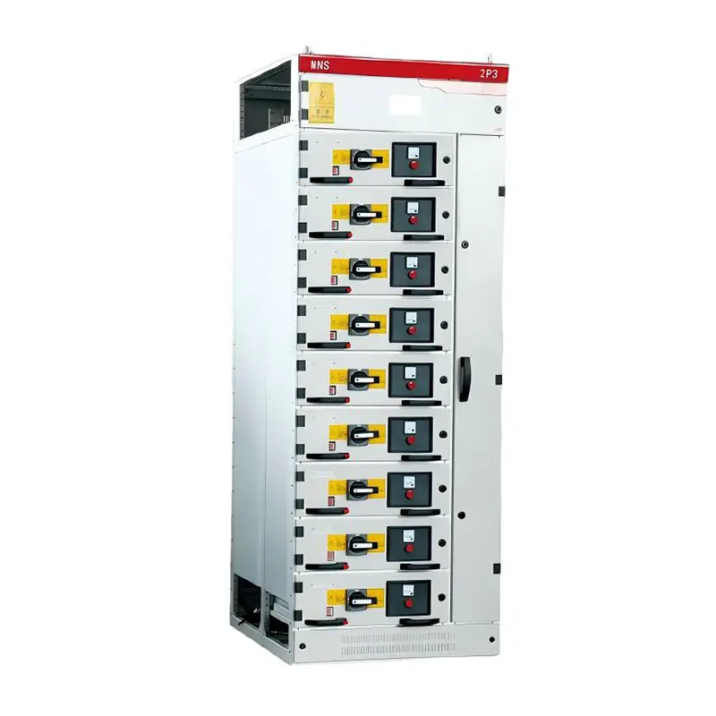
MNS Low Voltage Withdrawable Switchgear for Power Control
Type Designation
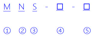
| 1 | Modularization & Modularity |
| 2 | New type |
| 3 | System |
| 4 | Main Circuit Scheme Number |
| 5 | Auxiliary Circuit Scheme Number |
Technical Parameters
| 1. Electrical Performance | ||
| Rated Insulation Voltage | 660V(1000)V | |
| Rated Operational Voltage | 380V、660V | |
| Main Busbar Maximum Operational Current | 5000A | |
| Main Busbar Rated Withstand Current | 100kA/1s | |
| Main Busbar Rated Peak Withstand Current | 220kA/1s | |
| Distribution Busbar (Vertical) Maximum Operational Current | 1000A | |
| Distribution Busbar (Vertical) Peak Current | ||
| Standard Type | 105kA(Max)/0.1s | |
| Reinforced Type | 176kA(Max)/0.1s | |
| 2. Protection Degree | ||
| Complies with IEC529, DIN 40050 Standards | ||
| IP30: Protection against solids >Φ2.5mm | ||
| IP40: Protection against solids >Φ1.0mm | ||
| IP54: Dust-protected & splashed water from any direction | ||
| (Contact manufacturer for IP54 customization) | ||
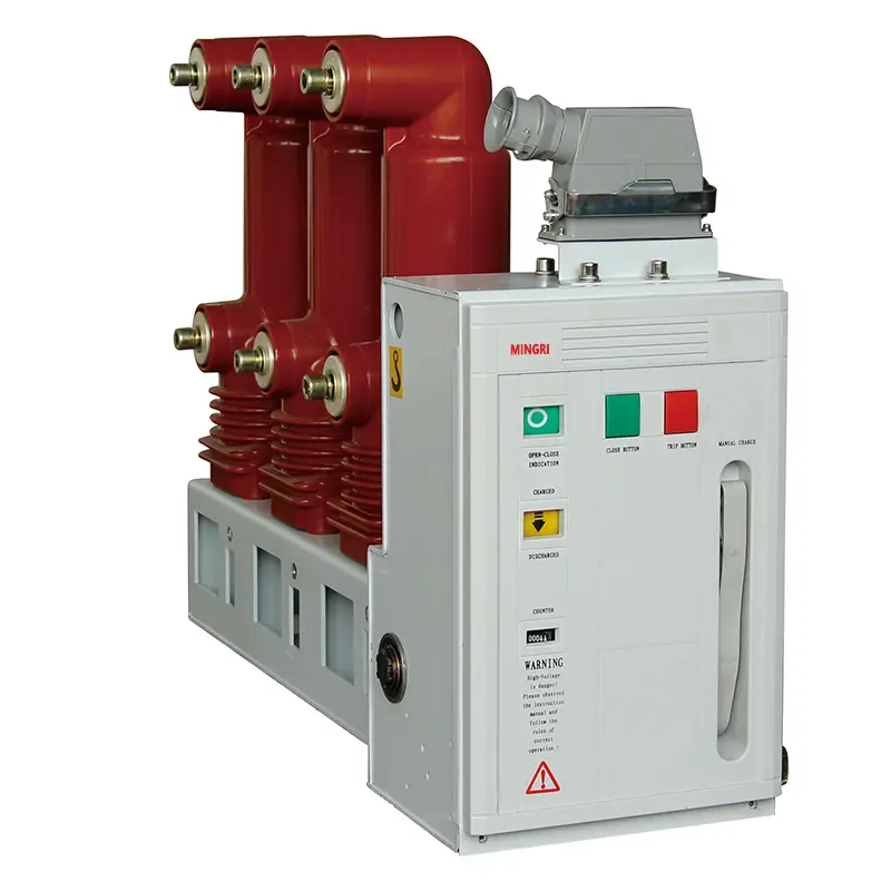
Type of switchgear
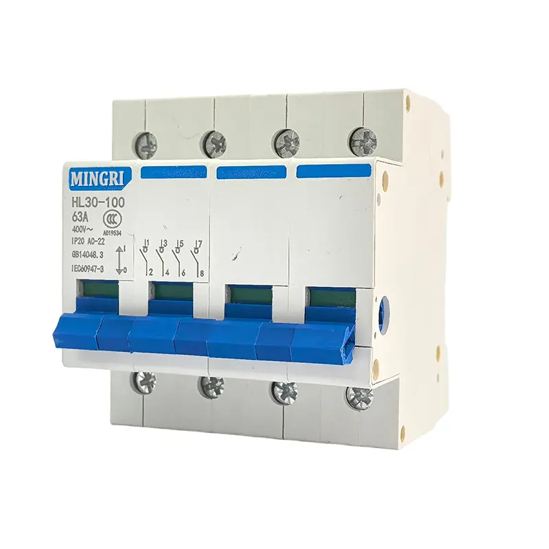
1. Motor Control Center Cabinet (MCC): assembled from large and small drawers, with main switches for each circuit using high break plastic case circuit breakers or rotary load switches with fuses
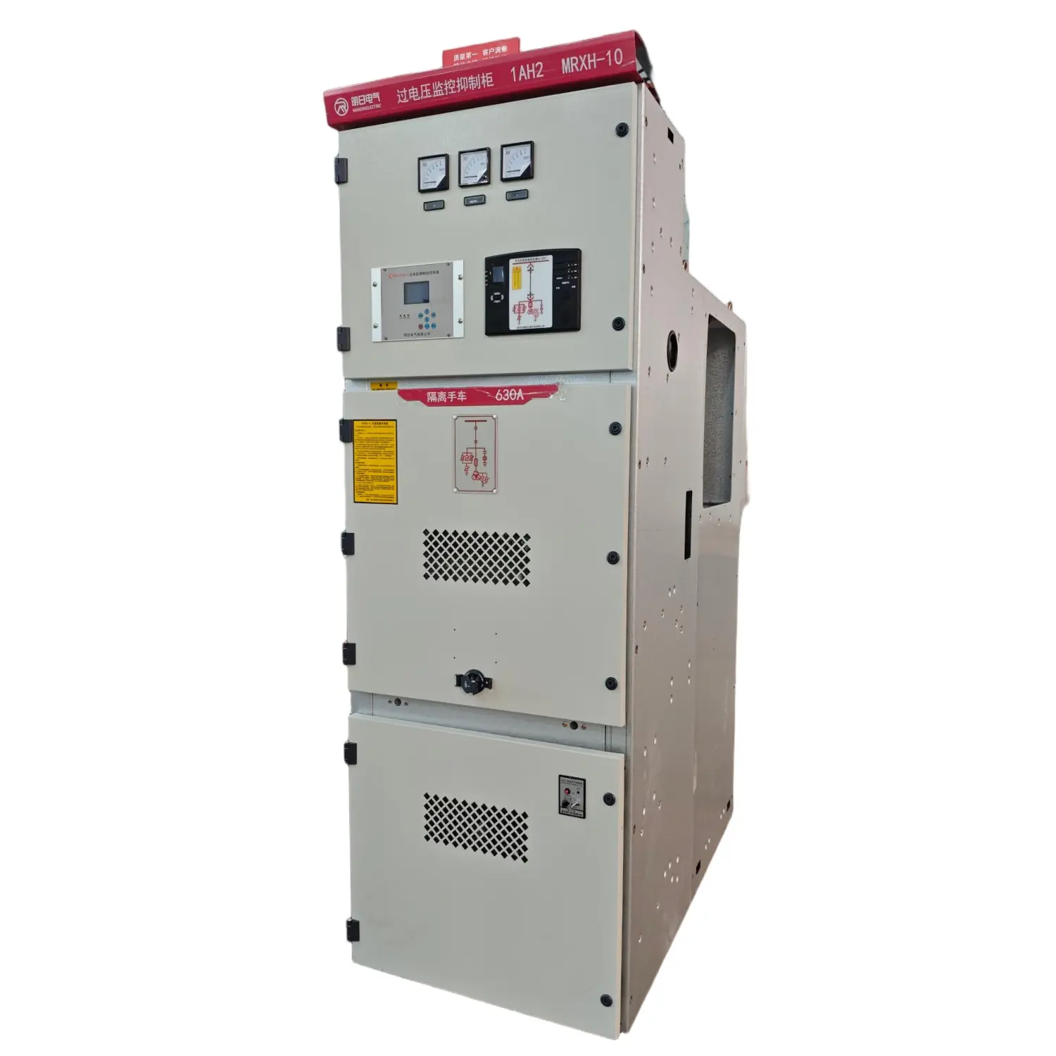
2. Power distribution center cabinet (PC): can use Emax, MT, 3WN, AH, ME series circuit breakers, etc
3. Power factor automatic compensation cabinet (with manual, automatic, and motion power factor compensation devices)
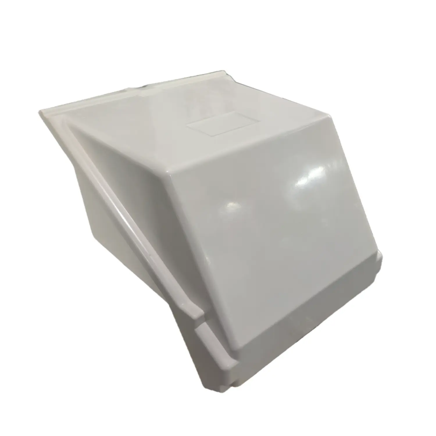
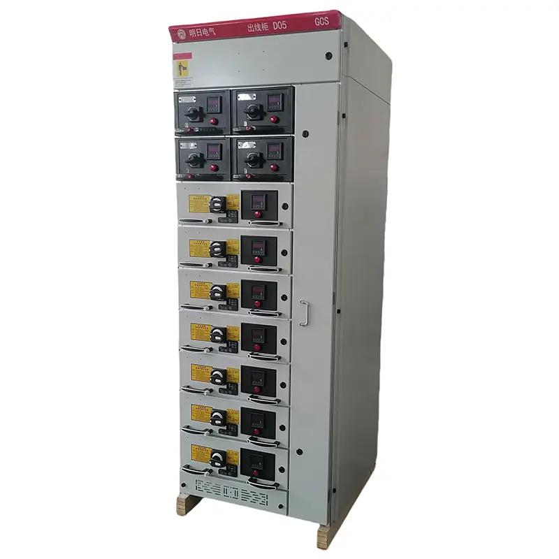
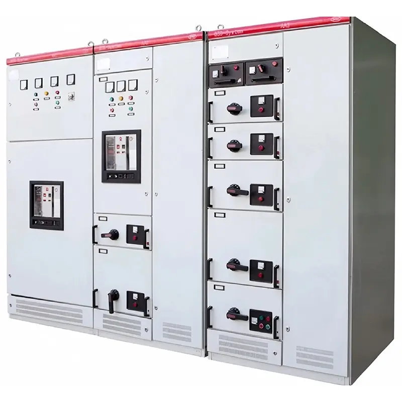
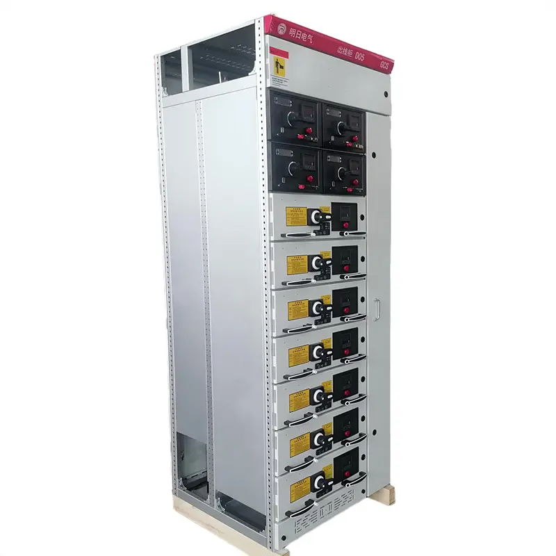
product Display
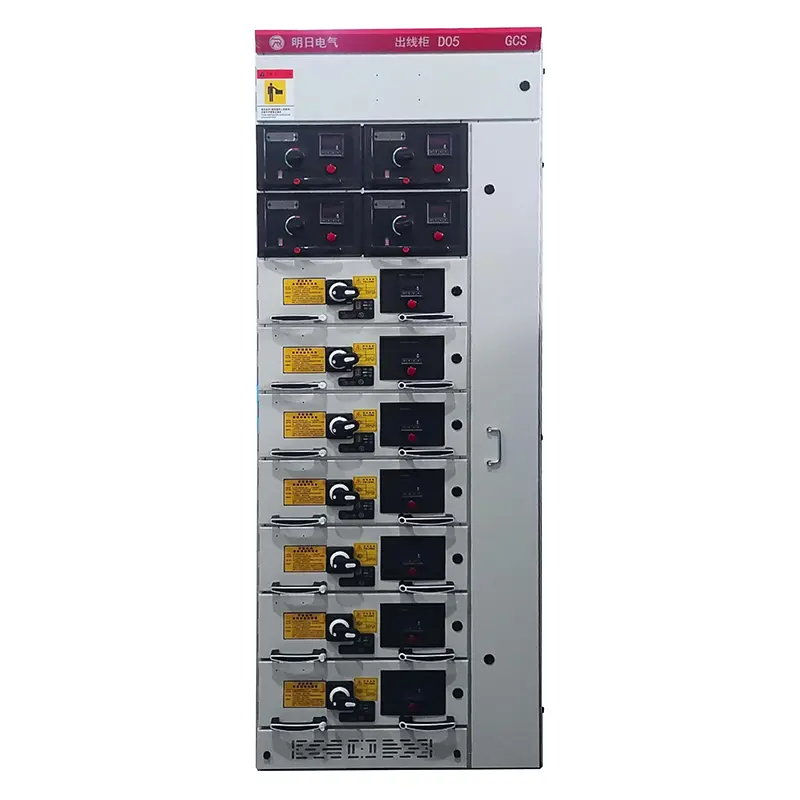
Cabinet Diagram
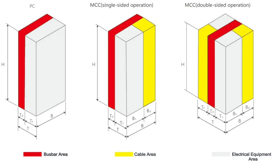
A Power Distribution Center (PC) Cabinet
| H | W | D | Note | |||||||||
| H | B | T | T1 | T2 | ||||||||
| 2200 | 400 | 1000 | 800 | 200 | Main Busbar Transfer | |||||||
| 2200 | 400 | 1000 | 800 | 200 | F1s-1250-2000 ME630-1605 | |||||||
| 2200 | 600 | 1000 | 800 | 200 | F2s-2500 | |||||||
| 2200 | 800 | 1000 | 800 | 200 | F4s-3200 ME2000-3200 | |||||||
| 2200 | 1000 | 1000 | 800 | 200 | F5s-4000 ME3205 | |||||||
| 2200 | 1200 | 1000 | 800 | 200 | ME4005 | |||||||
B Motor Control Center (MCC) Cabinet
| H | W | D | Note | |||||||||
| H | B | B1 | B2 | T | T1 | T2 | ||||||
| 2200 | 1000 | 600 | 400 | 600 | 400 | 200 | single-sided operation | |||||
| 2200 | 1000 | 600 | 400 | 1000 | 400 | 200 | double-sided operation | |||||
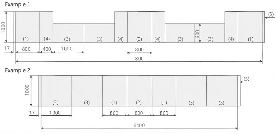
Assembly diagram
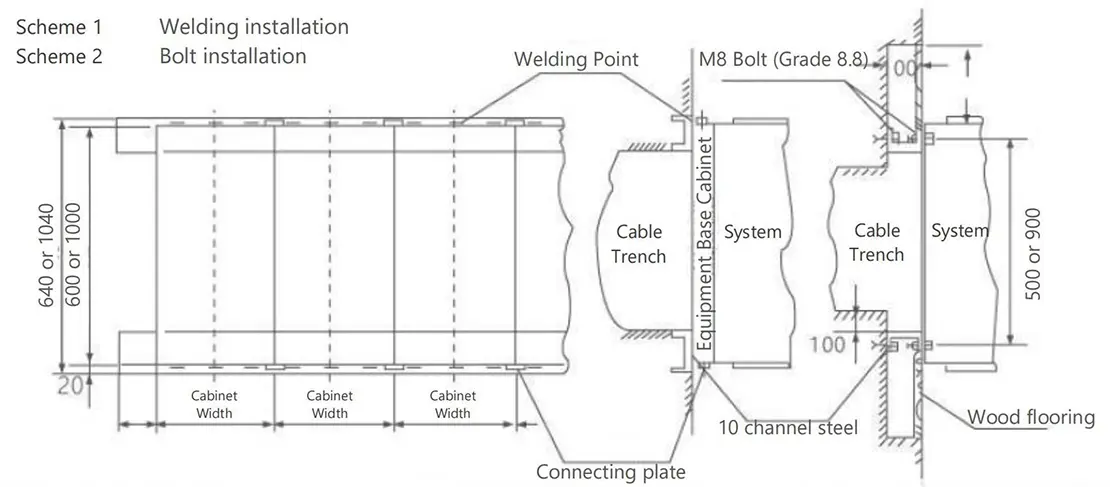
Installation diagram
Transportation and Storage Specifications
1. Transportation: Use transport angle plates with ≤120° wire rope angles; avoid direct contact with chassis when using tools.
2. Handling: Prevent tilting/vibration; for minor moves, only pry at test frame corners.
3. Components: No unauthorized disassembly of electrical parts; maintain rain/moisture protection.
4. Documentation: Includes packing list, certifications, manuals, drawings, keys, and matched spare parts.