


 Claire
 Mr.Fu
Mr.Fu

 Claire
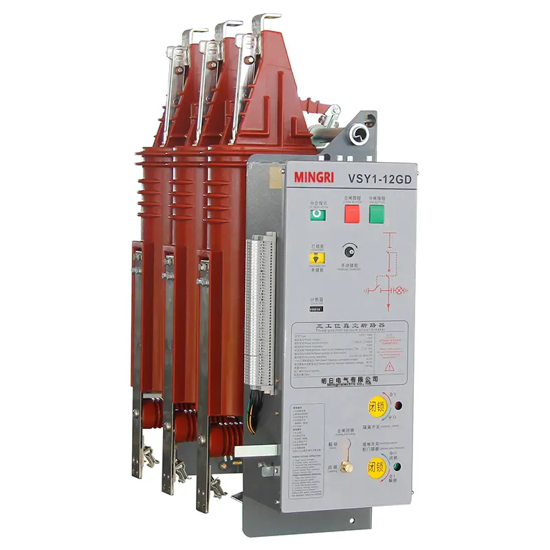
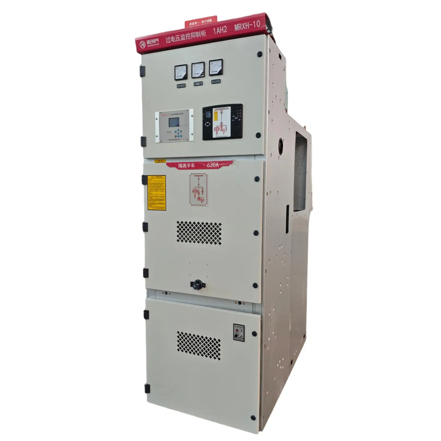


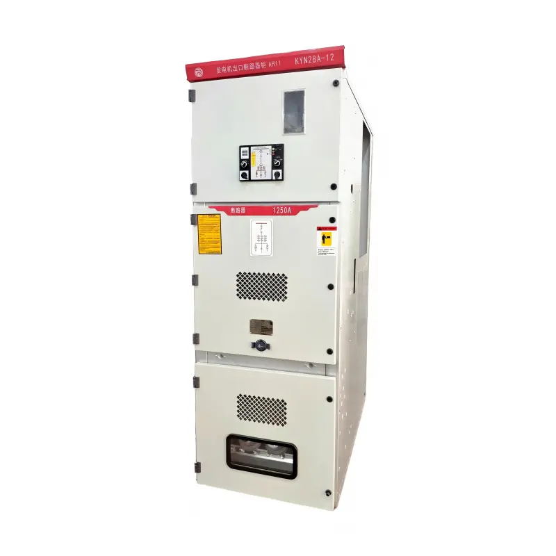
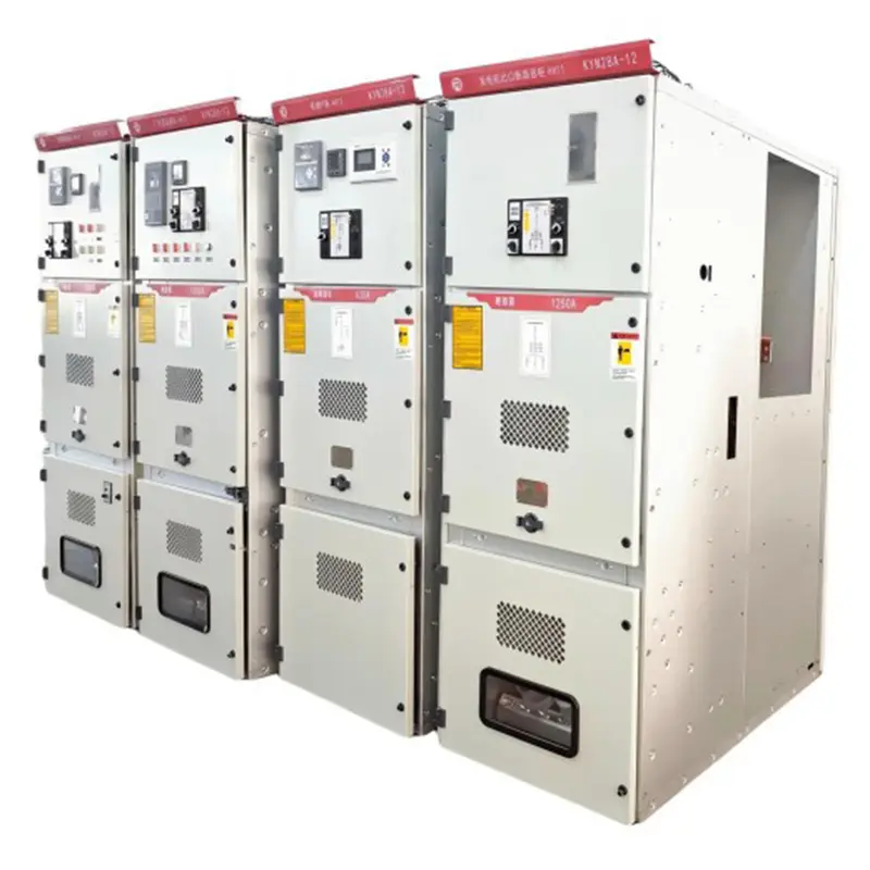
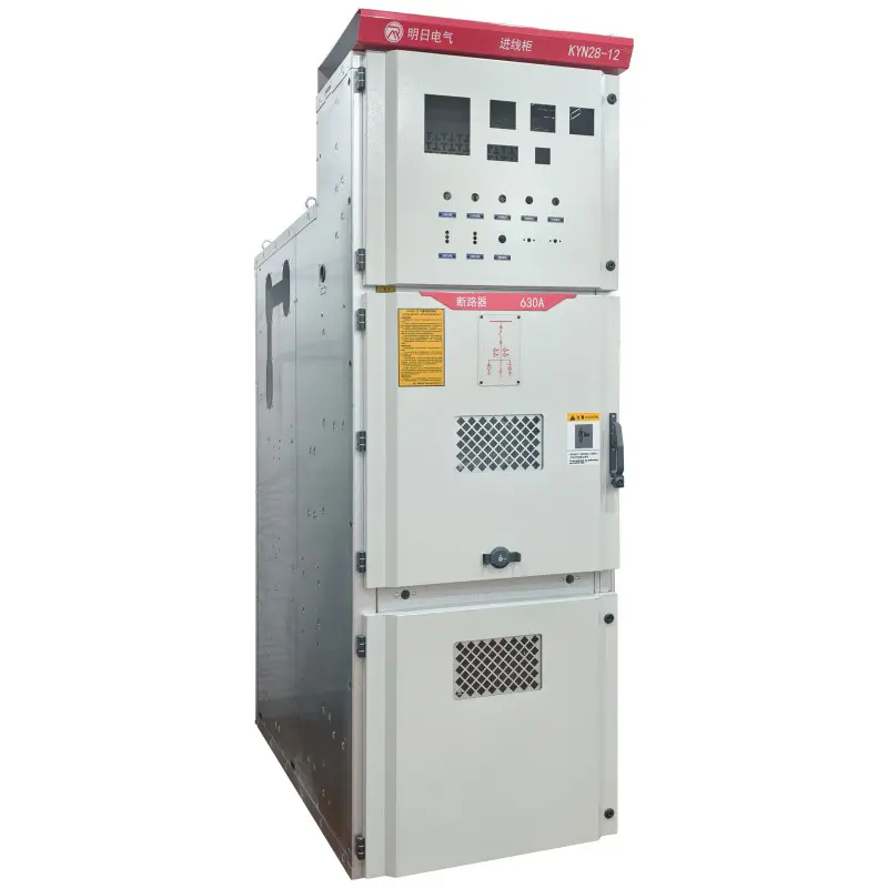
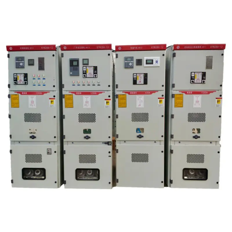
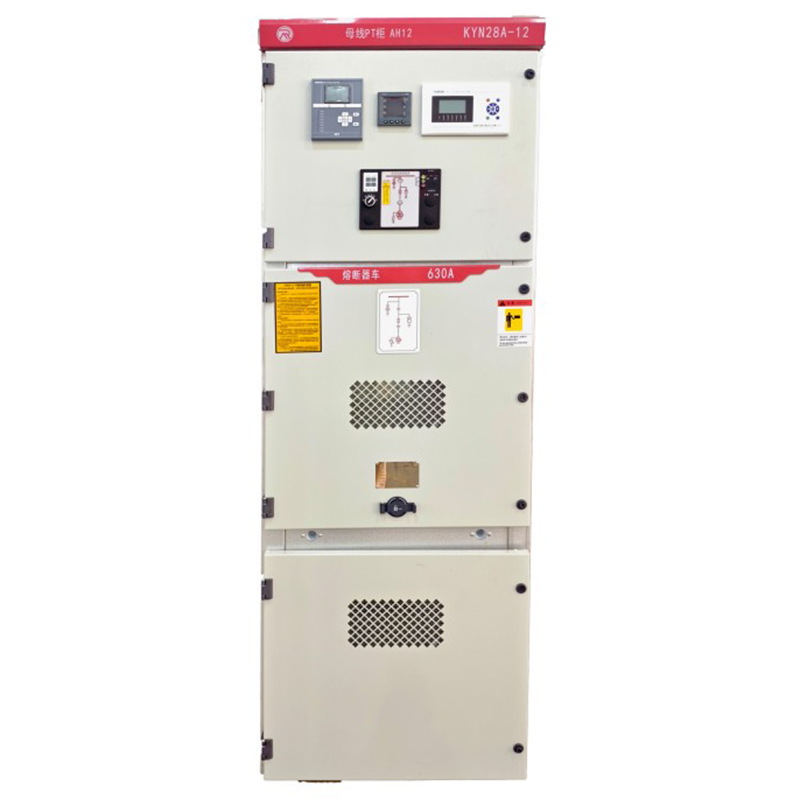
KYN28-12 Withdrawable Armored Metal-Enclosed Switchgear
Type Designation

| 1 | Armored Withdrawable Metal-Clad Switchgear |
| 2 | Withdrawable Type |
| 3 | Usage Conditions: (Indoor) |
| 4 | Design Serial Number |
| 5 | Rated Voltage (kV) |
| 6 | Main Circuit Diagram No. |
| 7 | Operating Mechanism Code, D: Electromagnetic; T: Spring |
| 8 | Rated Current (A) |
| 9 | Rated Short-Circuit Breaking Current (kA) |
Switchgear Technical Parameters
| Item | Unit | Value | |
| Rated Voltage | kV | 12 | |
| Main Bus Rated Current | Hz | 50 | |
| Rated Frequency | A | 630,1250,1600,2000,2500,3150 | |
| Rated Current | A | 630,1250,1600,2000,2500,3150 | |
| Earthed Circuit Rated Short-Time Withstand Current(2s) | kA | 13.9,17.4,21.8,27.4,34.8 | |
| Main Circuit Rated Short-Time Withstand Current (4s) | kA | 16,20,25,31.5,40 | |
| Rated Peak Withstand Current(Peak) | kA | 40,50,63,80,100 | |
| Rated Short-Circuit Breaking Current | kA | 25,31.5,40 | |
| Rated Insulation Level | 1min Power Frequency Withstand Voltage | kV | Phase-to-ground:42;Breaking:48 |
| Lightning Impulse Withstand Voltage | kV | Phase-to-ground:75;Breaking:48 | |
| Protection Class | Enclosure:IP4X | ||
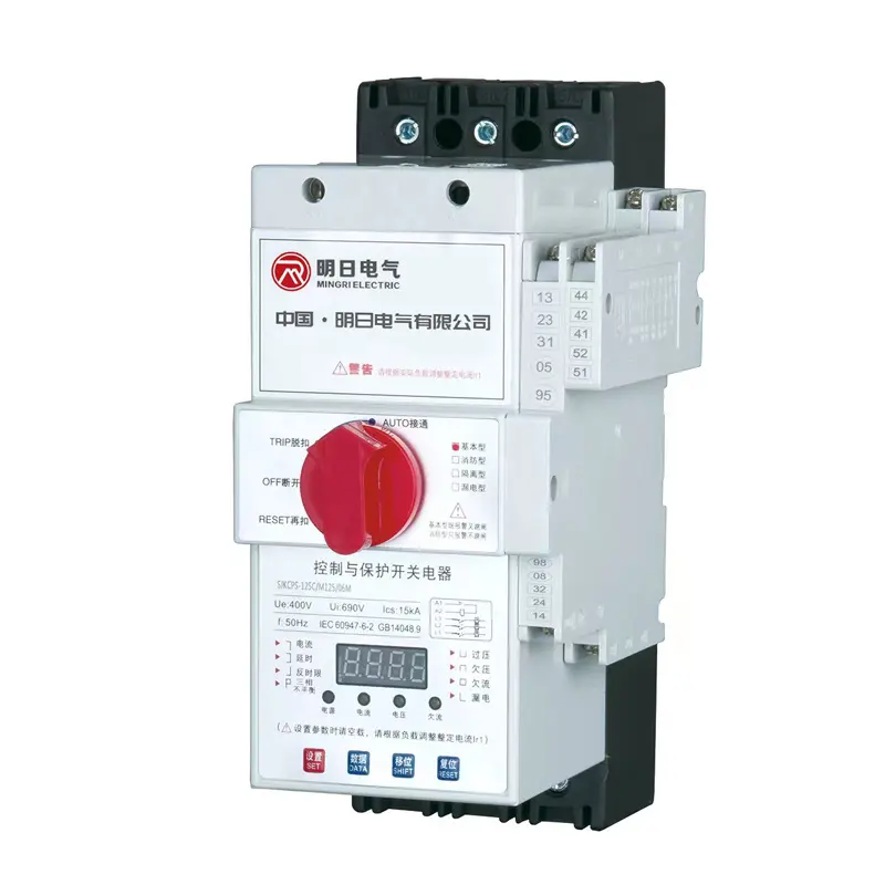
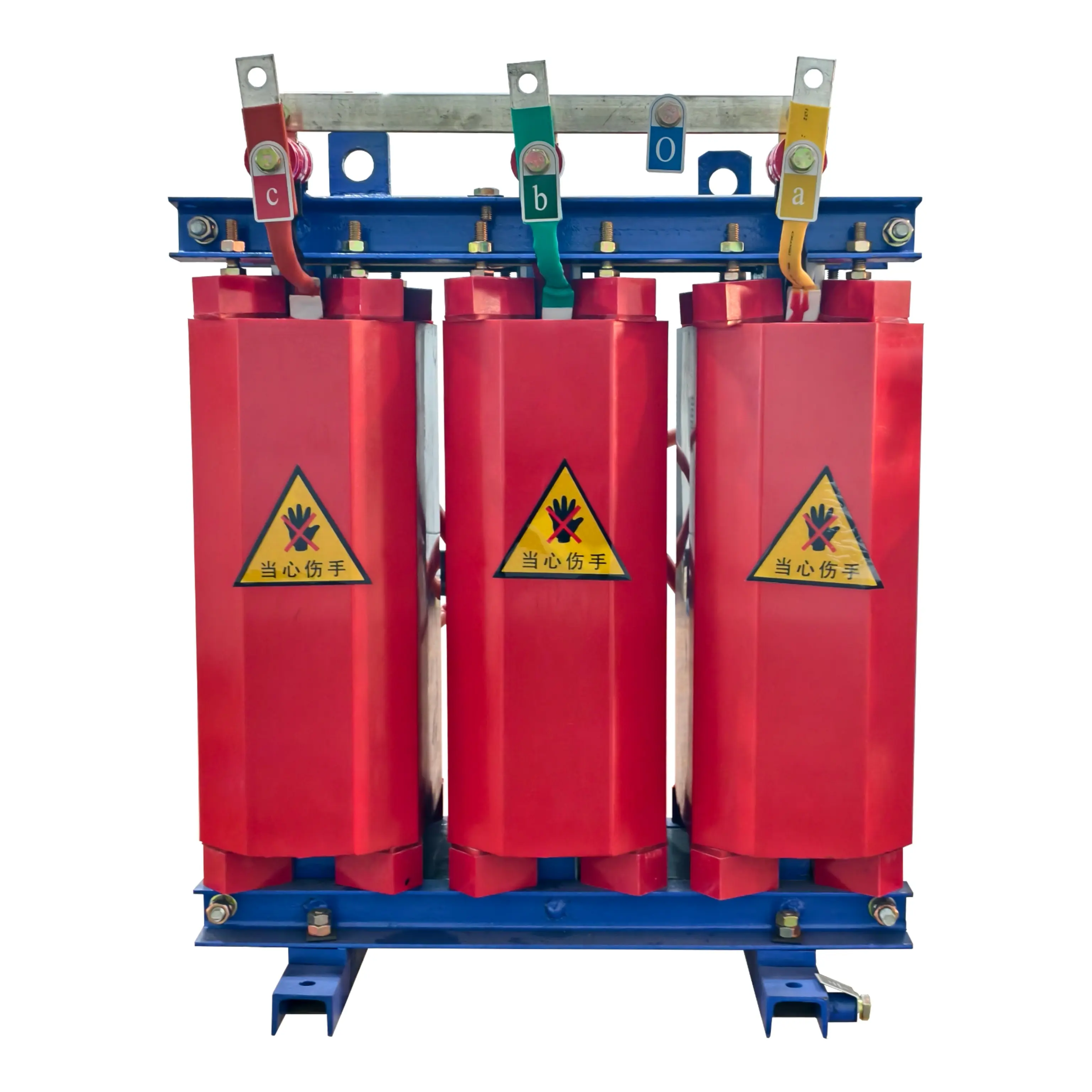
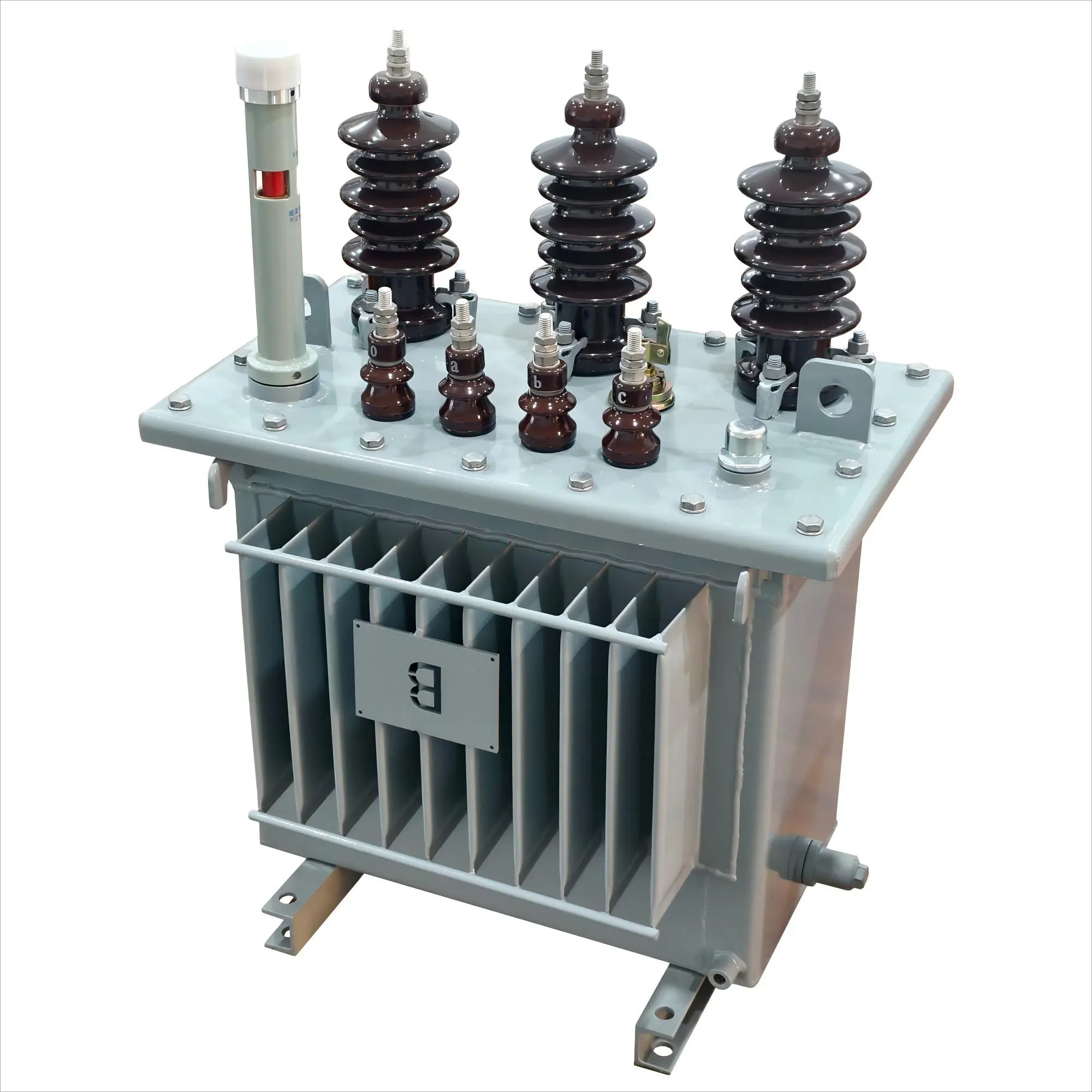
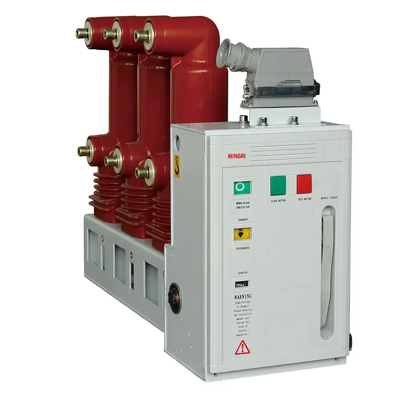
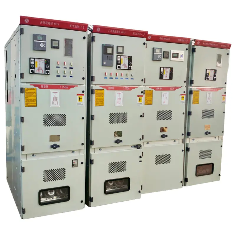
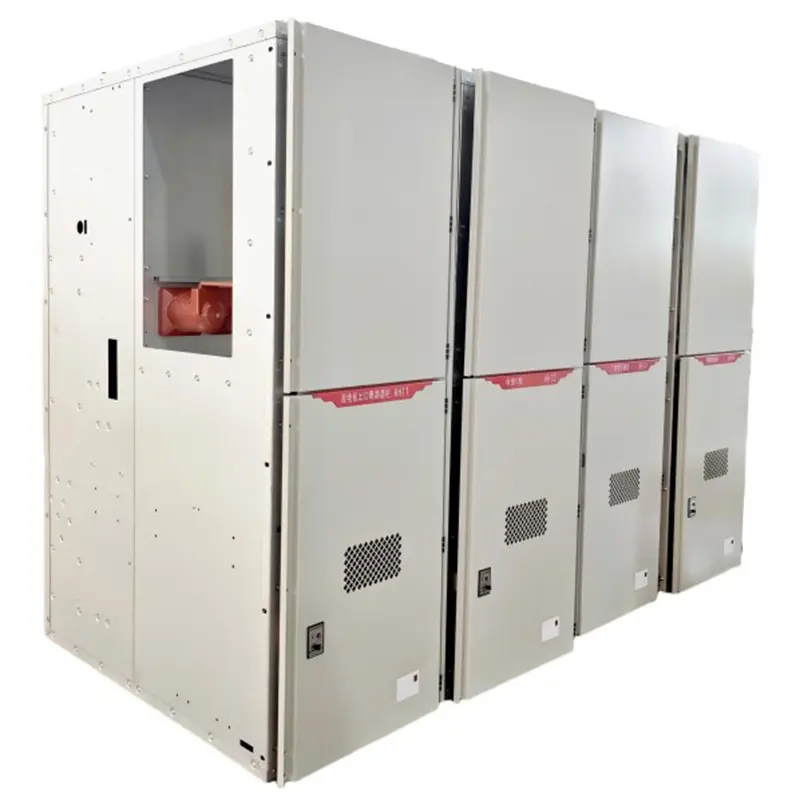
product Display
Switchgear Outline Dimensions
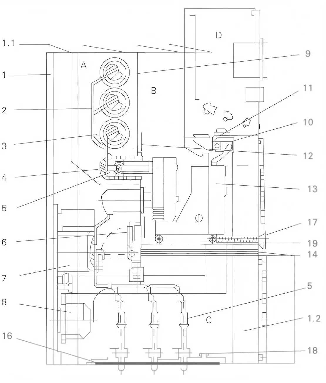
Fig.1: KYN28-12 Feeder Switchgear Cross-Sectional Diagram
| A.Busbar Compartment | 3.Main Busbar | 9.Removable Partition | 15.Cable Sealing End |
| B.Circuit Breaker Compartment | 4.Fixed Contact Assembly | 1O.Secondary Plug | 16.Base Plate |
| C.Cable Compartment | 5.Spring-Loaded Contact | 11.Auxiliary Switch | 17. Lead Screw Mechanism |
| D.Instrument Compartment | 6.Earthing Switch | 12. Movable Shutter | 18.Earthing Main Busbar |
| 1.Enclosure 1.1 Pressure Relief Pane1 1.2 Control Cable Cover Plate |
7.Current Transformer (CT) | 13.Withdrawable Trol1ey | 19. Removable Horizontal Partition |
| 2.Branch Busbar | 8.Voltage Transformer (VT) | 14.Earthing Switch 0perating Mechanism |
Ordering Notice
Product operating site and special requirements:
1. Provide product ordering drawings, which should include wiring diagrams and indicate transformer capacity, main component model specifications, distribution branch circuits, and capacity
2. When it is necessary to configure electric energy metering and reactive power automatic compensation devices, the requirements for the configuration of the metering meter and transformer should be provided, and the capacity of the compensation capacitor should be indicated
3. Specify the requirements for surface treatment of the product