


 Claire
 Mr.Fu
Mr.Fu

 Claire
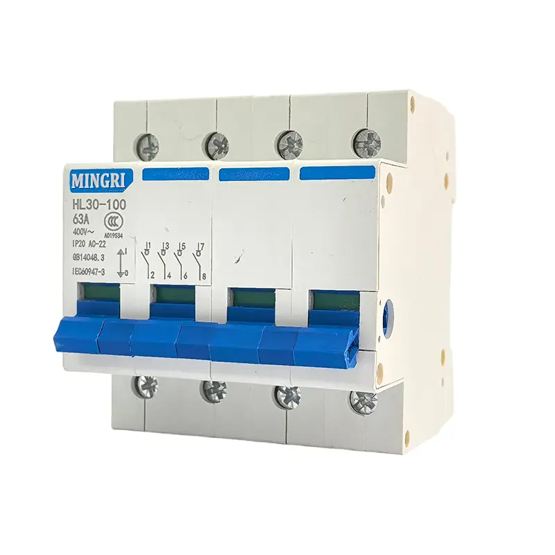


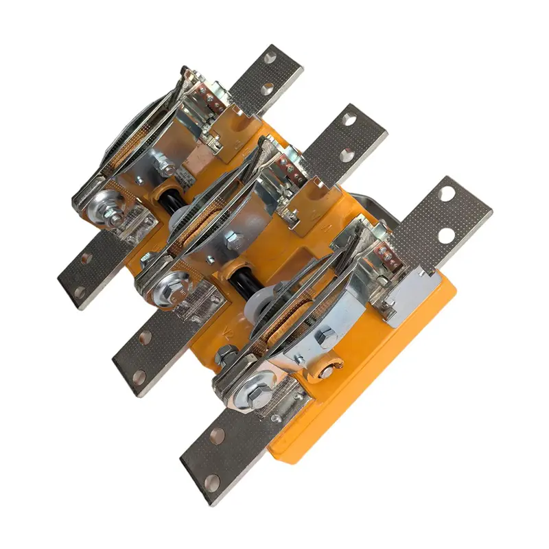
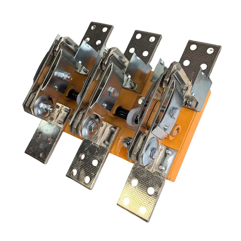
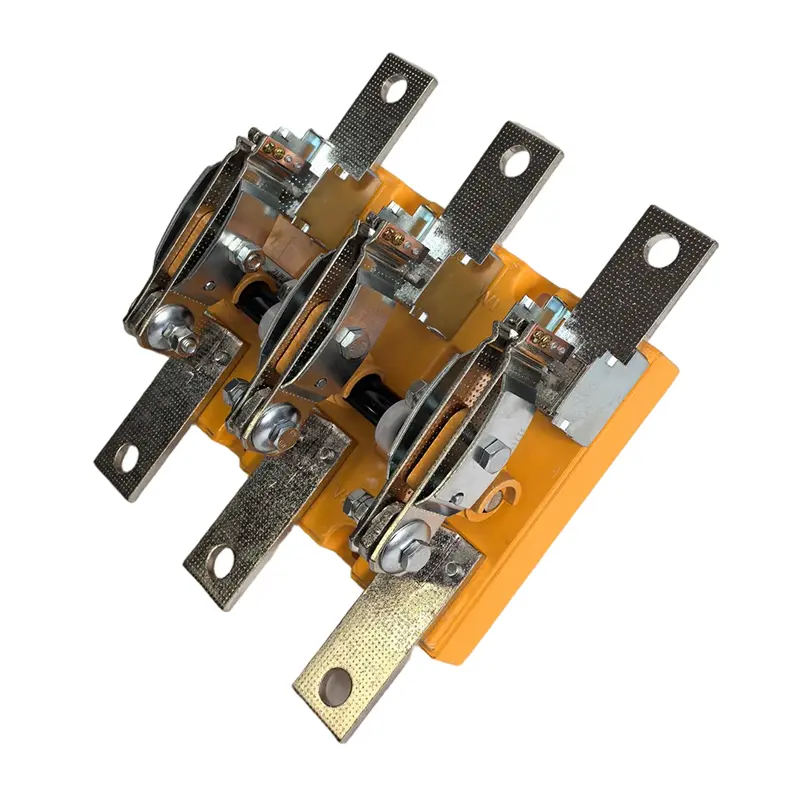
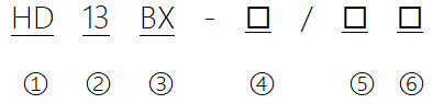
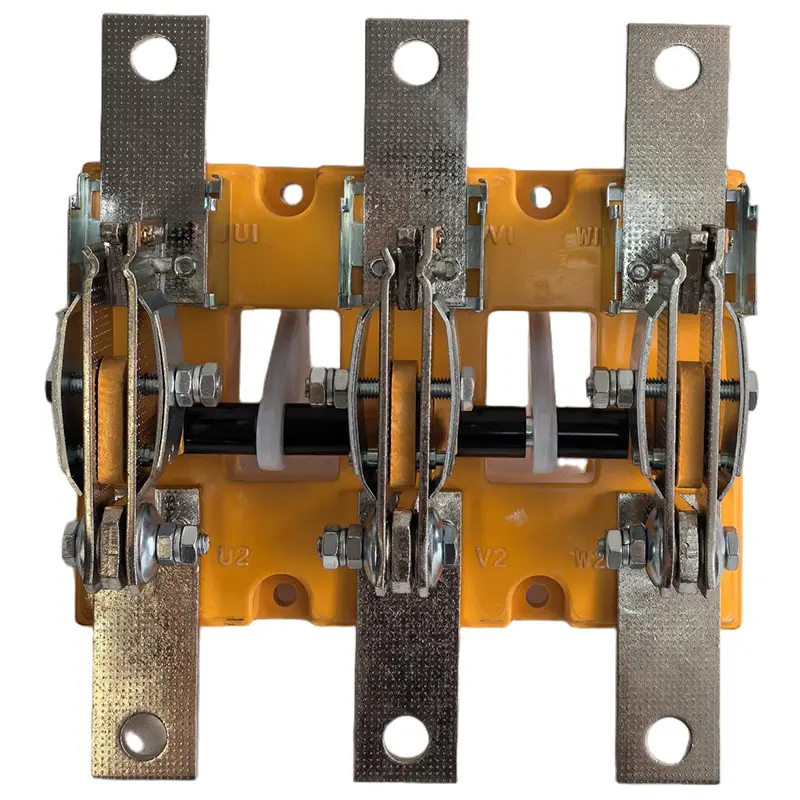
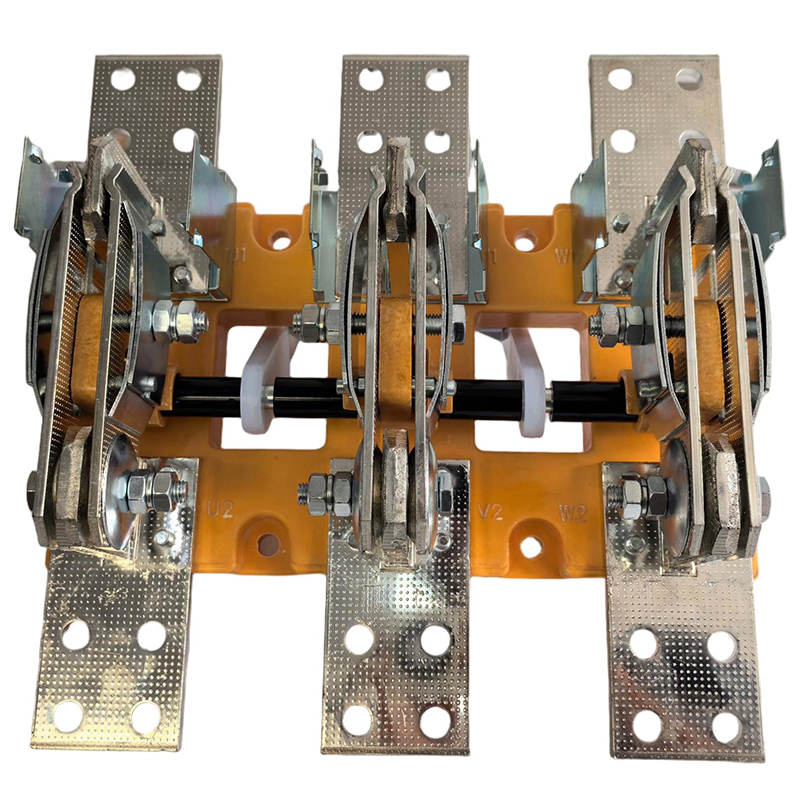
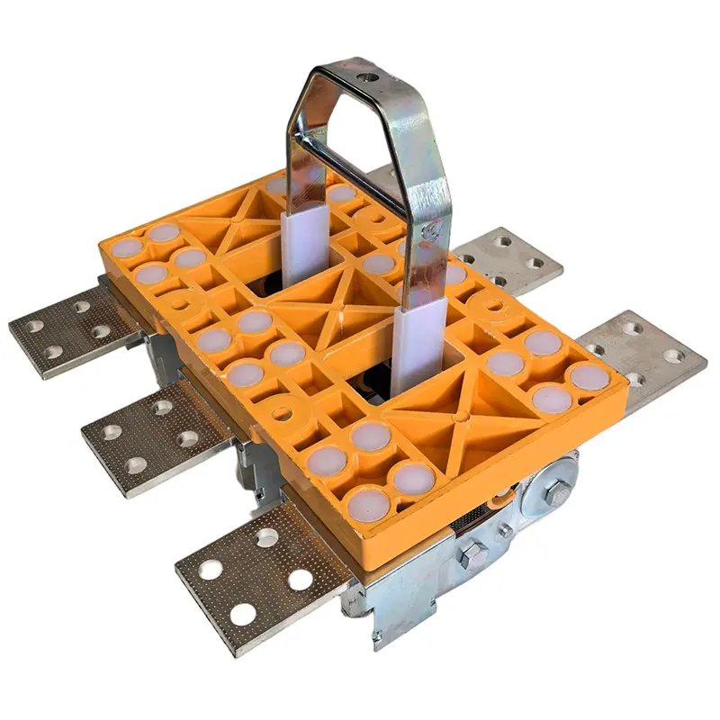
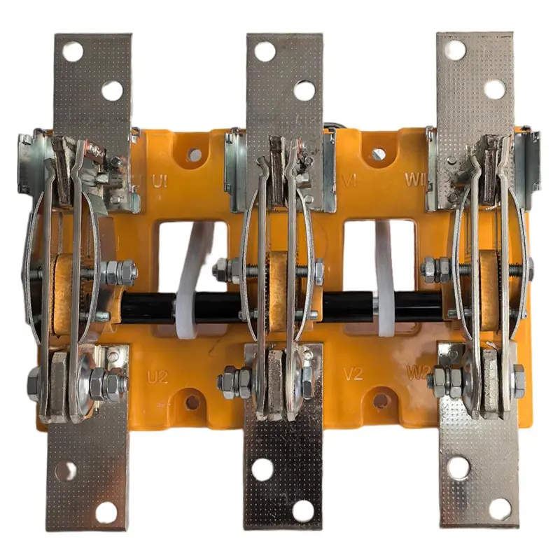
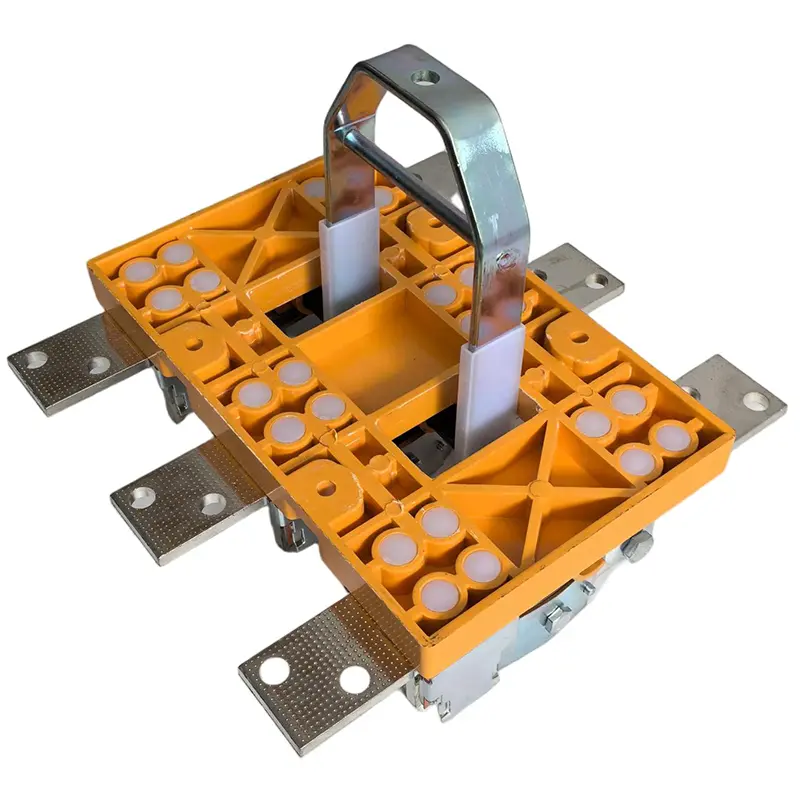
HD13BX Single Throw Rotary Knife Switch
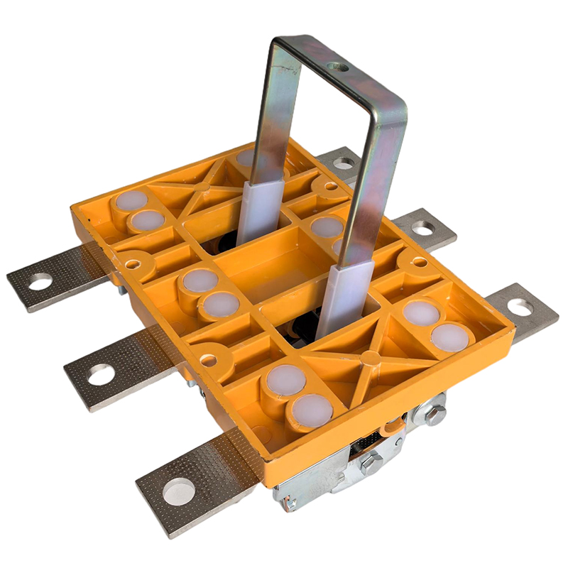
Type Designation
| 1 | Category Code: "HD": Open-type Knife Switch; |
| 2 | Design Code: "11": Central Handle Type "13": Central Lever Operation Mechanism Type |
| 3 | With "BX" indicates rotary operation type; Without "BX" indicates lever operation type |
| 4 | Conventional Free-air Thermal Current (A) |
| 5 | Number of Poles (1,2,3,4) |
| 6 | "0" indicates without arc extinguishing device; "1" indicates with arc extinguishing device For central handle type: "8" indicates front terminal connection; "9" indicates rear terminal connection; None indicates only one connection method, i.e., front terminal connection |
Technical Parameters
| Conventional Free-air Thermal Current (A) | 100 | 200 | 400 | 600,630 | 1000 | 1500 | 2000 |
| Rated Operational Current (A) | 100 | 200 | 400 | 600,630 | 1000 | 1500 | 2000 |
| Rated Operational Voltage (V) | AC380V | ||||||
| Insulation Voltage (V) | 1000 | ||||||
| Making and Breaking Capacity (A) AC380V,cosA=0.72~0.8 | 100 | 200 | 400 | 600,630 | 1000 | 1500 | |
| Mechanical Endurance (operations) | 10000 | 10000 | 10000 | 5000 | 5000 | 5000 | 3000 |
| Electrical Endurance (operations) Note: Not applicable to central handle type. | 300 | 200 | 200 | 200 | 200 | 100 | |
| 1s Short-time Withstand Current (kA) | 4 | 4 | 20 | 25 | 20 | 30 | 24 |
| Operating Force (N) | ≤300 | ≤300 | ≤400 | ≤400 | ≤400 | ≤400 | ≤400 |
product Display
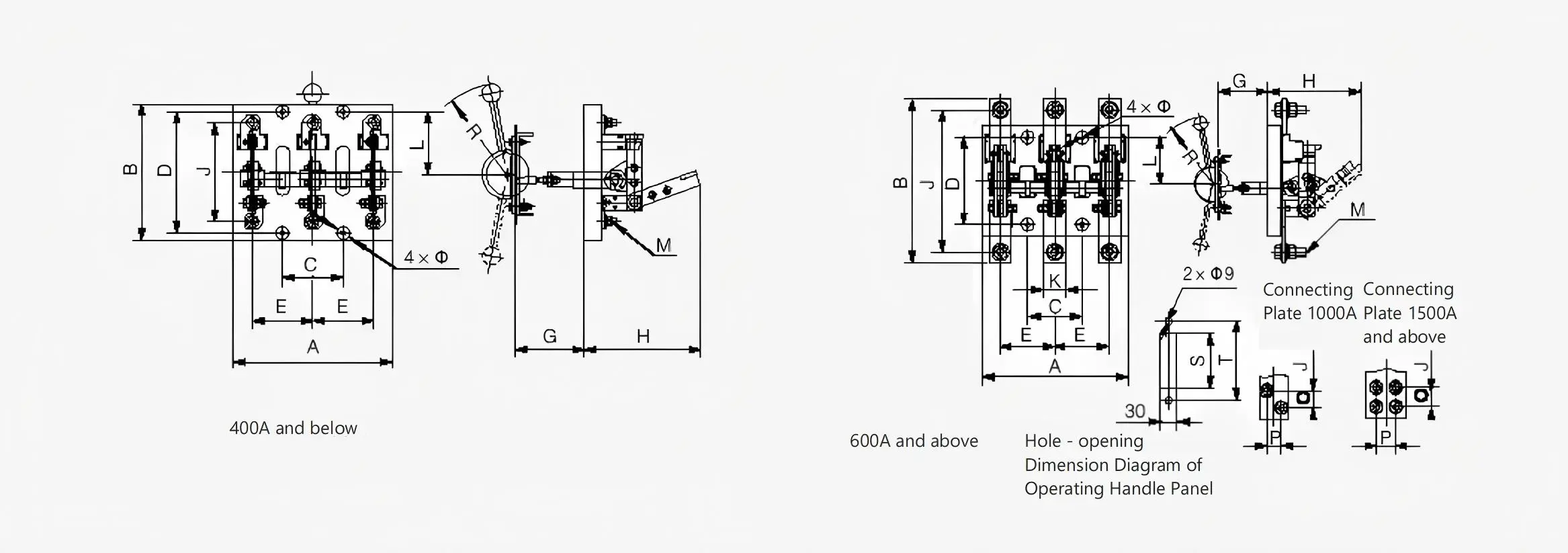
HD13BX Outline and Installation Dimensions
↓HD13 Central Lever Operation Mechanism Open-type Knife Switch Outline and Installation Dimensions, see table below.
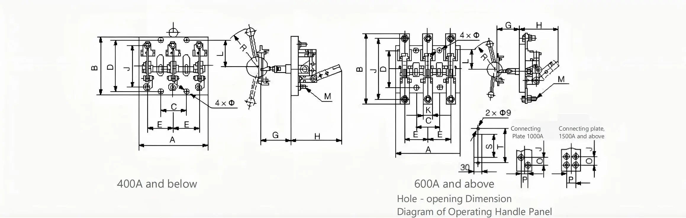
| Model | Specification | 100A,200A | 400A | 600A | 1000A | ||||||||
| 2P | 3P | 4P | 2P | 3P | 4P | 2P | 3P | 4P | 2P | 3P | 4P | ||
| HD13 Central Lever Operation Mechanism Open-type Knife Switch | A | 190 | 210 | 300 | 220 | 245 | 335 | 240 | 260 | 360 | 280 | 320 | 460 |
| B | 200 | 200 | 200 | 210 | 210 | 210 | 294 | 294 | 294 | 314 | 314 | 314 | |
| C | 160 | 80 | 160 | 180 | 90 | 180 | 200 | 100 | 200 | 240 | 120 | 240 | |
| D | 160 | 160 | 160 | 160 | 160 | 160 | 160 | 160 | 160 | 160 | 160 | 160 | |
| E | 80 | 80 | 80 | 90 | 90 | 90 | 100 | 100 | 100 | 120 | 120 | 120 | |
| G Front | 350~370 | 350~370 | 350~370 | 350~370 | |||||||||
| G Rear | 245~265 | 245~265 | 245~265 | 245~265 | |||||||||
| H | 160 | 160 | 160 | 185 | 185 | 185 | 190 | 190 | 190 | 230 | 230 | 230 | |
| J | 130 | 130 | 130 | 166 | 166 | 166 | 254 | 254 | 254 | 238 | 238 | 238 | |
| K | - | - | - | - | - | - | 40 | 40 | 40 | 50 | 50 | 50 | |
| L | 75 | 75 | 75 | 75 | 75 | 75 | 80 | 80 | 80 | 80 | 80 | B0 | |
| O | - | - | - | - | - | - | - | - | - | 25 | 25 | 25 | |
| P | - | - | - | - | - | - | - | - | - | 25 | 25 | 25 | |
| R | 180 | 180 | 180 | 180 | 180 | 180 | 180 | 180 | 180 | 230 | 230 | 230 | |
| S | 100 | 100 | 100 | 100 | 100 | 100 | 100 | 100 | 100 | 100 | 100 | 100 | |
| T | 146 | 146 | 146 | 146 | 146 | 146 | 146 | 146 | 146 | 146 | 146 | 146 | |
| M | 8 | 8 | 8 | 12 | 12 | 12 | 16 | 16 | 16 | 12 | 12 | 12 | |
| A | 7 | 7 | 7 | 7 | 7 | 7 | 9 | 9 | 9 | 9 | 9 | 9 | |
| Model | Specification | 1500A | 2000A | 3000A(2500A) | ||||||
| 2P | 3P | 4P | 2P | 3P | 4P | 2P | 3P | 4P | ||
| HD13 Central Lever Operation Mechanism Open-type Knife Switch | A | 310 | 350 | 510 | 500 | 500 | 680 | 600 | 600 | 800 |
| B | 354 | 354 | 354 | 360 | 360 | 360 | 400 | 400 | 400 | |
| C | 260 | 130 | 260 | 180 | 180 | 360 | 200 | 200 | 400 | |
| D | 160 | 160 | 160 | 160 | 160 | 160 | 160 | 160 | 160 | |
| E | 130 | 130 | 130 | 180 | 180 | 180 | 200 | 200 | 200 | |
| G Front | 350~370 | 350~370 | 350~370 | |||||||
| G Rear | 245~265 | 345~265 | 245~265 | |||||||
| H | 235 | 235 | 235 | 230 | 230 | 230 | 235 | 235 | 235 | |
| J | 254 | 254 | 254 | 244 | 244 | 244 | 264 | 264 | 264 | |
| K | 70 | 70 | 70 | 100 | 100 | 100 | 120 | 120 | 120 | |
| L | 80 | 80 | 80 | 80 | 80 | 80 | 80 | 80 | 80 | |
| O | 35 | 35 | 35 | 40 | 40 | 40 | 45 | 45 | 45 | |
| P | 35 | 35 | 35 | 55 | 55 | 55 | 68 | 68 | 68 | |
| R | 230 | 230 | 280 | 280 | 280 | 280 | 280 | 280 | 280 | |
| S | 100 | 100 | 130 | 130 | 130 | 130 | 140 | 140 | 140 | |
| T | 146 | 146 | 164 | 164 | 164 | 164 | 180 | 180 | 180 | |
| M | 12 | 12 | 12 | 12 | 12 | 12 | 16 | 16 | 16 | |
| A | 9 | 9 | 9 | 11 | 11 | 11 | 11 | 11 | 11 | |
↓HD13 Central Lever Operation Mechanism Knife Switch Outline and Installation Dimensions, see table below.
| Model | Specification | 100A,200A | 400A | 600A,630A | 1000A | ||||||||
| 2P | 3P | 4P | 2P | 3P | 4P | 2P | 3P | 4P | 2P | 3P | 4P | ||
| HD13 Central Lever Operation Mechanism Knife Switch | A | 190 | 210 | 300 | 220 | 245 | 335 | 240 | 260 | 360 | 280 | 320 | 460 |
| B | 200 | 200 | 200 | 210 | 210 | 210 | 294 | 294 | 294 | 314 | 314 | 314 | |
| C | 160 | 80 | 160 | 180 | 90 | 180 | 200 | 100 | 200 | 240 | 120 | 240 | |
| D | 160 | 160 | 160 | 160 | 160 | 160 | 160 | 160 | 160 | 160 | 160 | 160 | |
| E | 80 | 80 | 80 | 90 | 90 | 90 | 100 | 100 | 100 | 120 | 120 | 120 | |
| G(Front) | 350~370 | 350~370 | 350~370 | 350~370 | |||||||||
| G(Rear) | 245~265 | 245~265 | 245~265 | 245~265 | |||||||||
| H | 160 | 160 | 160 | 185 | 185 | 185 | 190 | 190 | 190 | 230 | 230 | 230 | |
| J | 130 | 130 | 130 | 166 | 166 | 166 | 254 | 254 | 254 | 238 | 238 | 238 | |
| K | - | - | - | - | - | - | 40 | 40 | 40 | 50 | 50 | 50 | |
| L | 75 | 75 | 75 | 75 | 75 | 75 | 80 | 80 | 80 | 80 | 80 | 80 | |
| O | - | - | - | - | - | - | - | - | - | 25 | 25 | 25 | |
| P | - | - | - | - | - | - | - | - | - | 25 | 25 | 25 | |
| R | 180 | 180 | 180 | 180 | 180 | 180 | 180 | 180 | 180 | 230 | 230 | 230 | |
| S | 100 | 100 | 100 | 100 | 100 | 100 | 100 | 100 | 100 | 100 | 100 | 100 | |
| T | 146 | 146 | 146 | 146 | 146 | 146 | 146 | 146 | 146 | 146 | 146 | 146 | |
| M | 8 | 8 | 8 | 12 | 12 | 12 | 16 | 16 | 16 | 12 | 12 | 12 | |
| A | 8.5 | ||||||||||||
| Model | Specification | 1500A | 2000A | 3000A(2500A) | ||||||
| 2P | 3P | 4P | 2P | 3P | 4P | 2P | 3P | 4P | ||
| HD13 Central Lever Operation Mechanism Knife Switch | A | 310 | 350 | 510 | 450 | 500 | 680 | 520 | 600 | 800 |
| B | 354 | 354 | 354 | 360 | 360 | 360 | 400 | 400 | 400 | |
| C | 260 | 130 | 260 | 170 | 170 | 360 | 190 | 190 | 400 | |
| D | 160 | 160 | 160 | 160 | 160 | 160 | 160 | 160 | 160 | |
| E | 130 | 130 | 130 | 340 | 170 | 180 | 380 | 190 | 200 | |
| G(Front) | 350~370 | 350~370 | 350~370 | |||||||
| G(Rear) | 245~265 | 245~265 | 245~265 | |||||||
| H | 235 | 235 | 235 | 230 | 230 | 230 | 235 | 235 | 235 | |
| J | 254 | 254 | 254 | 244 | 244 | 244 | 264 | 264 | 264 | |
| K | 70 | 70 | 70 | 100 | 100 | 100 | 120 | 120 | 120 | |
| L | 80 | 80 | 80 | 80 | 80 | 80 | 80 | 80 | 80 | |
| O | 35 | 35 | 35 | 40 | 40 | 40 | 45 | 45 | 45 | |
| P | 35 | 35 | 35 | 55 | 55 | 55 | 68 | 68 | 68 | |
| R | 230 | 230 | 280 | 280 | 280 | 280 | 280 | 280 | 280 | |
| S | 100 | 100 | 130 | 130 | 130 | 130 | 140 | 140 | 140 | |
| T | 146 | 146 | 164 | 164 | 164 | 164 | 180 | 180 | 180 | |
| M | 12 | 12 | 12 | 12 | 12 | 12 | 16 | 16 | 16 | |
| A | 9 | 9 | 9 | 11 | 11 | 11 | 11 | 11 | 11 | |