


 Claire
 Mr.Fu
Mr.Fu

 Claire
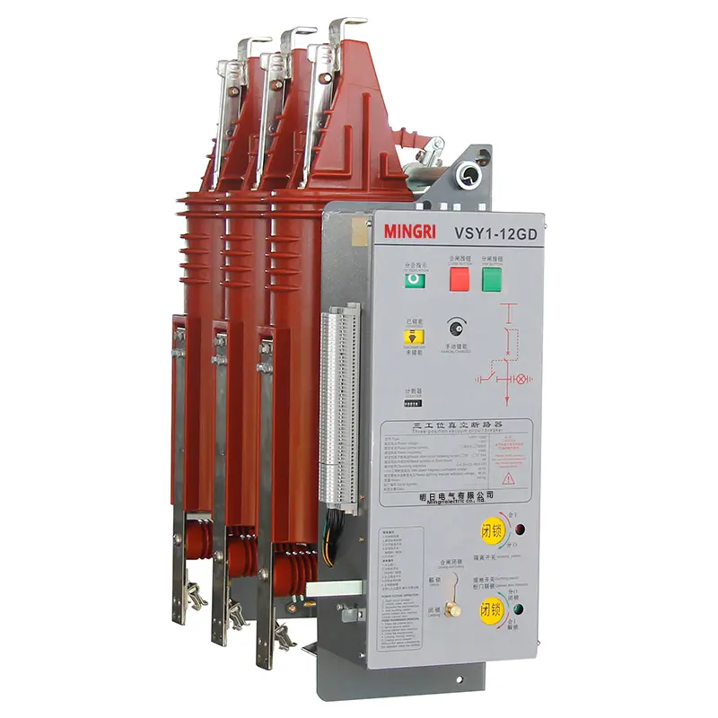
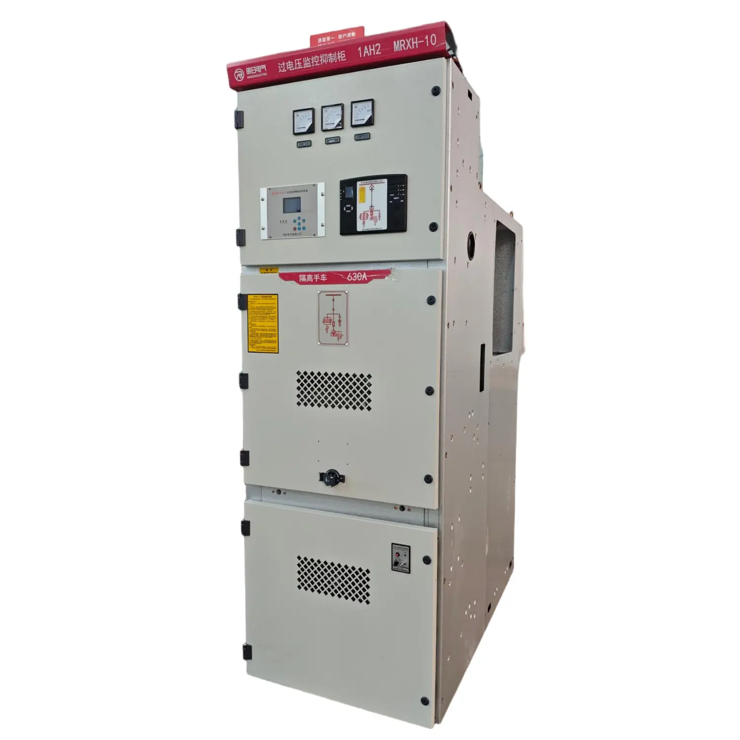
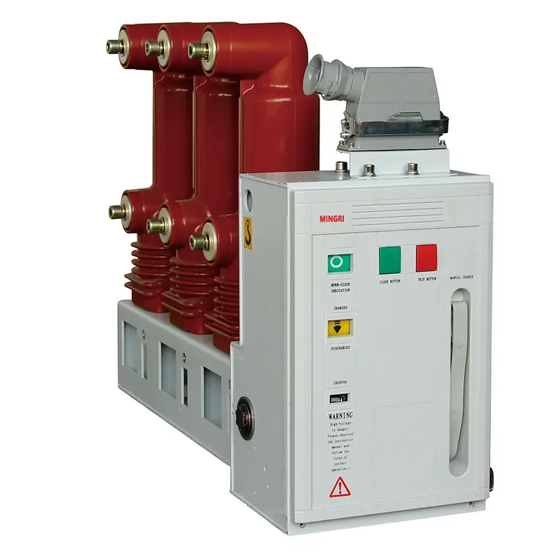

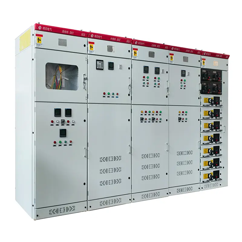
GCS Low Voltage Withdrawable Switchgear Panel for Power Distribution
Type Designation
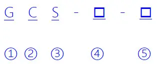
| 1 | Enclosed switchgear |
| 2 | Withdrawable switchgear |
| 3 | Electrical System |
| 4 | Main circuit scheme number |
| 5 | Auxiliary circuit scheme number |
Technical Parameters
| Main circuit Rated Voltage (V) | AC 380(400),(660) | |
| Auxiliary circuit Rated Voltage (V) | AC 220,380(400) DC 110,220 | |
| Rated Frequency (Hz) | 50(60) | |
| Rated Insulation Voltage (V) | 660(1000) | |
| Rated Current (A) | Horizontal Busbar | ≤4000 |
| Vertical Busbar (MCC) | 1000 | |
| Busbar Rated Short-Time Withstand Current (kA/1s) | 50,80 | |
| Busbar Rated Peak Withstand Current (kA/0.1s) | 105,176 | |
| Power-Frequency Withstand Voltage (V/1min) | Main circuit | 2500 |
| Auxiliary circuit | 1760 | |
| Busbar | 3-Phase 4-Wire System | A.B.C.PE.N |
| 3-Phase 5-Wire System | A.B.C.PE.N | |
| operating mode | IP30.IP40 | |
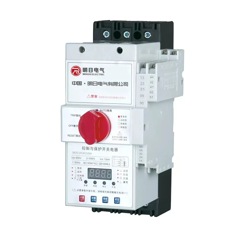
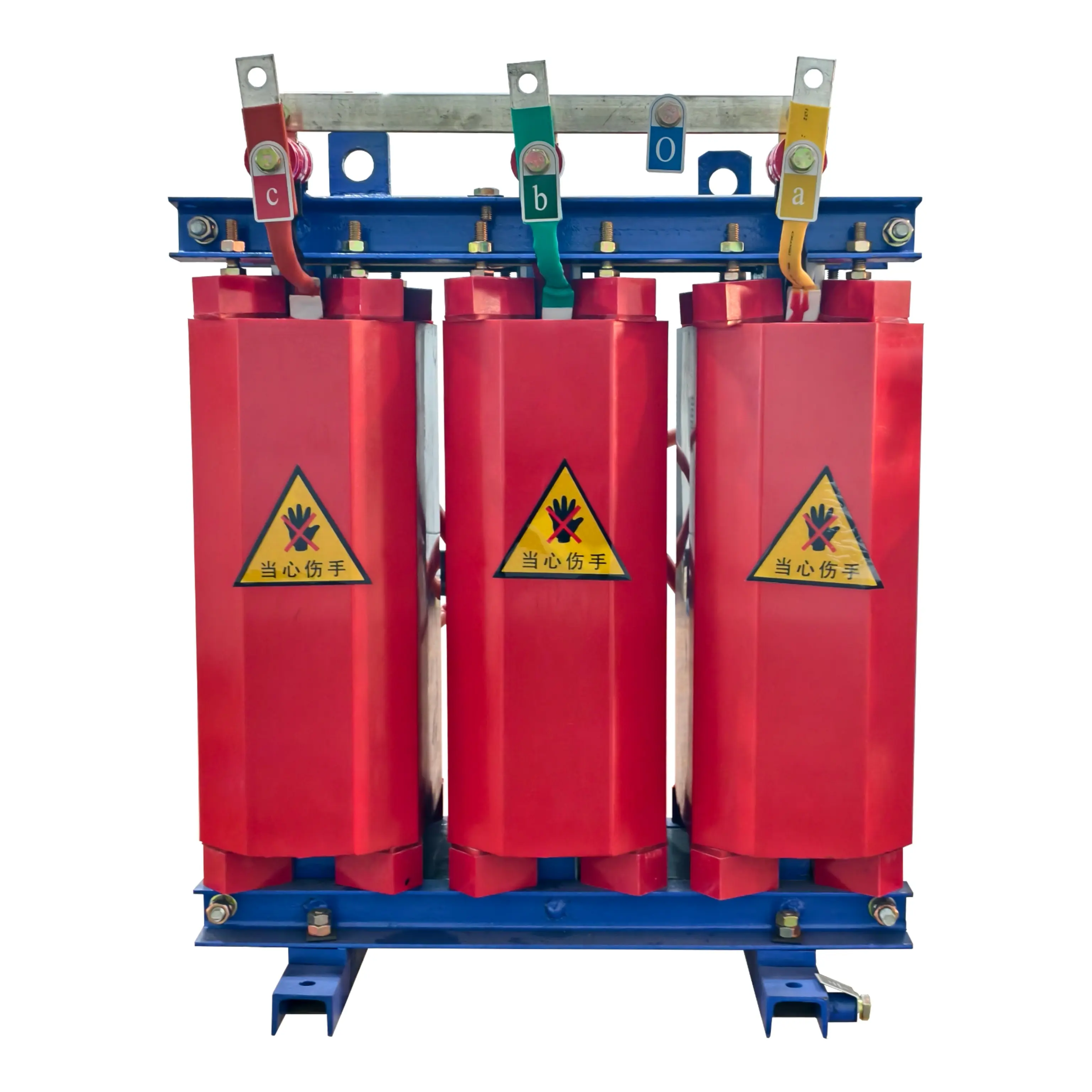
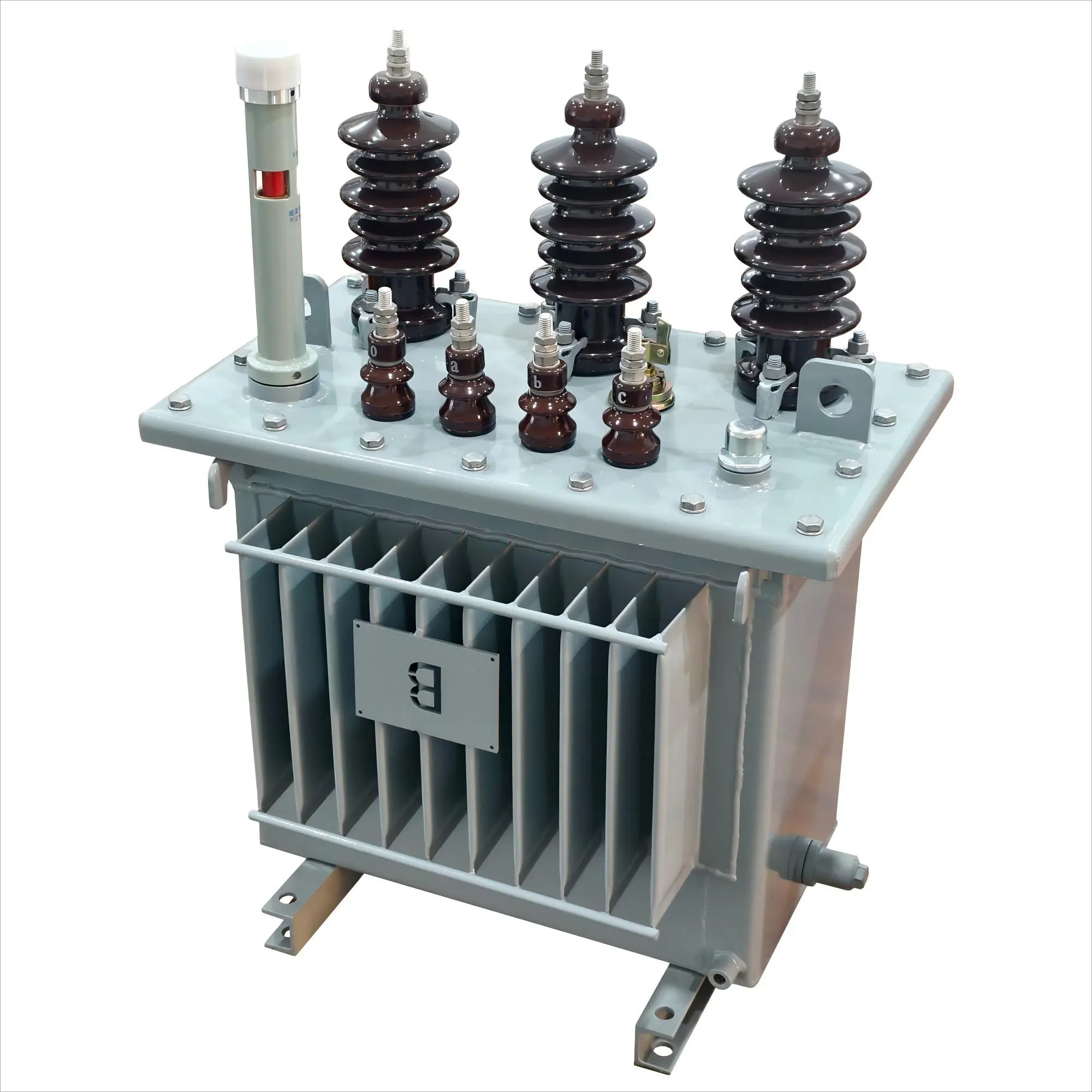
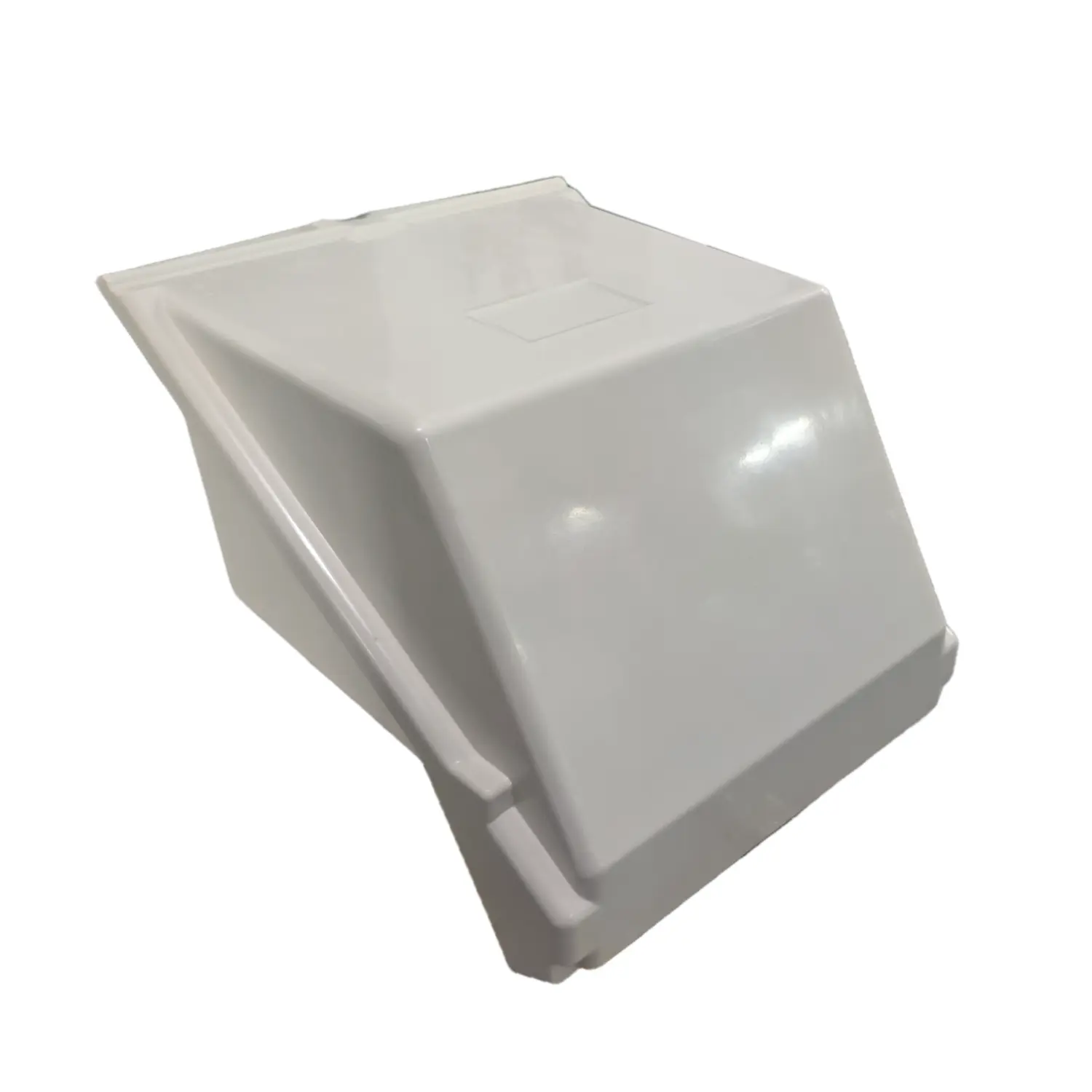
product Display
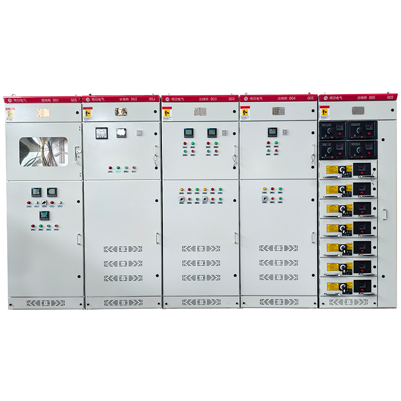
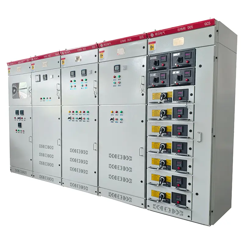
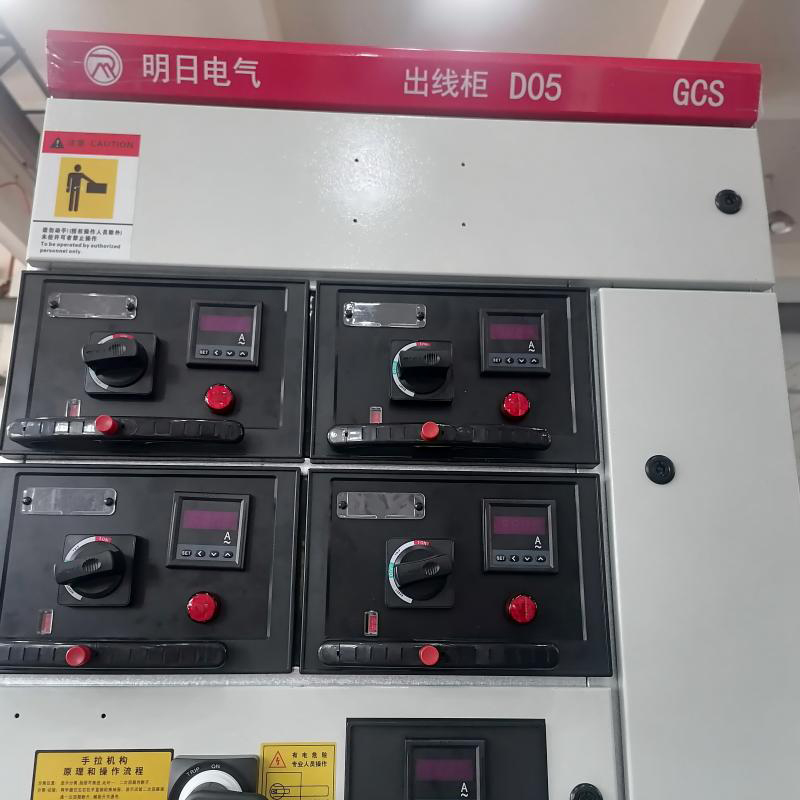
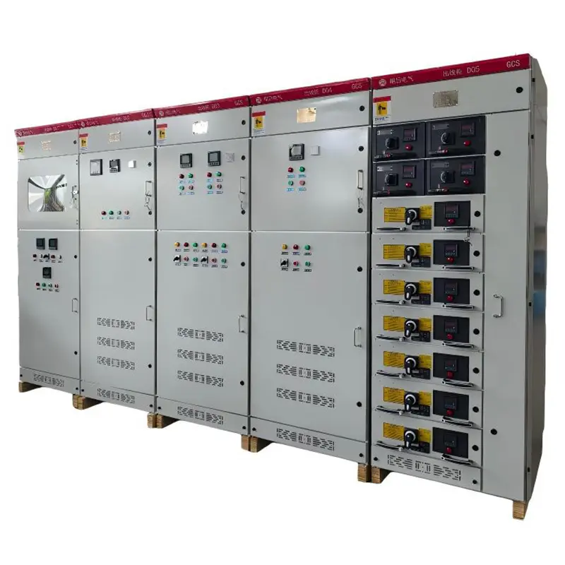
Figure 1. Installation Drawing
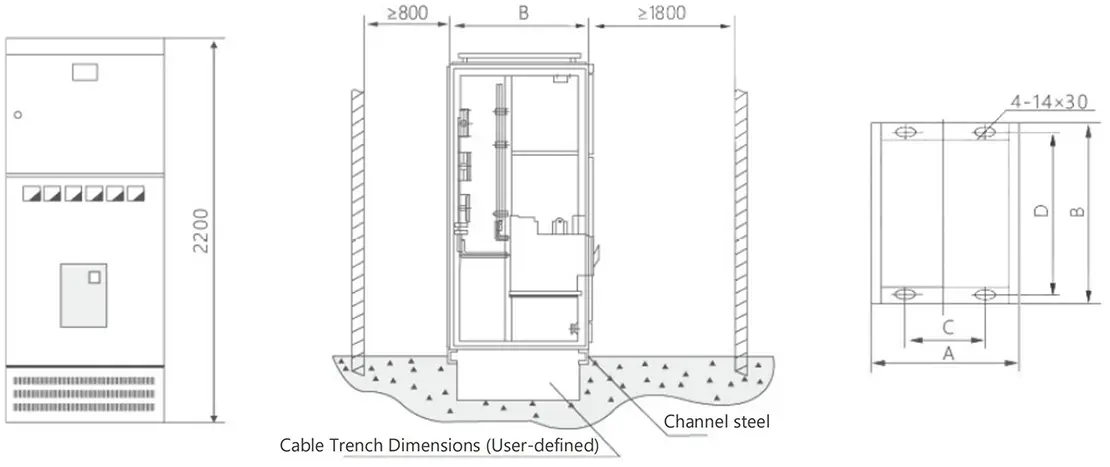
| H | 2200 | |||||||||
| W | 400 | 600 | 800 | 1000 | ||||||
| D | 800 | 1000 | 800 | 1000 | 600 | 800 | 1000 | 600 | 800 | 1000 |
| General Cabinet Code | A | B | C | D | Notes |
| GCS-TG1010-4 | 1000 | 1000 | 850 | 956 | Tie Cabinet |
| GCS-TG0810-4 | 800 | 1000 | 650 | 956 | Incoming Cabinet |
| GCS-TG0808-4 | 800 | 800 | 650 | 756 | Incoming Cabinet |
| GCS-TG0608-4 | 600 | 800 | 450 | 756 | Incoming Cabinet |
Figure 2. PC Cabinet Installation Schematic
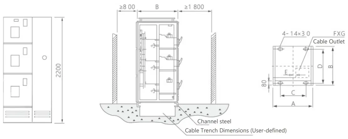
| General Cabinet Code | A | B | C | D | E | F×G |
| GCS-TG1010-2 | 1000 | 1000 | 850 | 956 | 60 | 400×400 |
| GCS-TG0810-2 | 800 | 1000 | 650 | 956 | 160 | 200×400 |
| GCS-TG1008-2 | 1000 | 800 | 850 | 756 | 60 | 400×400 |
| GCS-TG0808-2 | 800 | 800 | 650 | 756 | 160 | 200×400 |
Figure 3. MCC Cabinet Installation Schematic
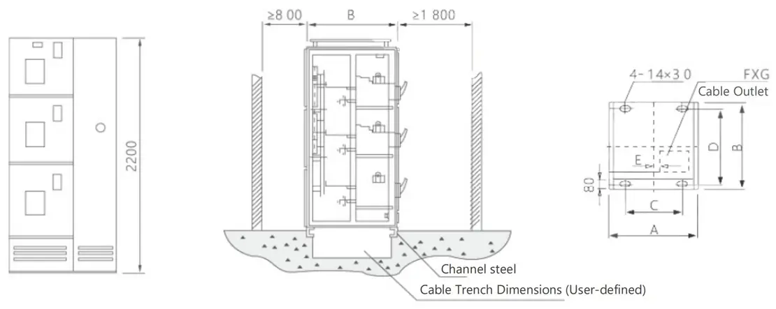
| General Cabinet Code | A | B | C | D | E | F×G |
| GCS-TG1006-1 | 1000 | 600 | 850 | 556 | 60 | 400x350 |
| GCS-TG0806-1 | 800 | 600 | 650 | 556 | 160 | 200x350 |
Ordering Notice
Product operating site and special requirements:
1. Provide product ordering drawings, which should include wiring diagrams and indicate transformer capacity, main component model specifications, distribution branch circuits, and capacity
2. When it is necessary to configure electric energy metering and reactive power automatic compensation devices, the requirements for the configuration of the metering meter and transformer should be provided, and the capacity of the compensation capacitor should be indicated
3. Specify the requirements for surface treatment of the product