


 Claire
 Mr.Fu
Mr.Fu

 Claire
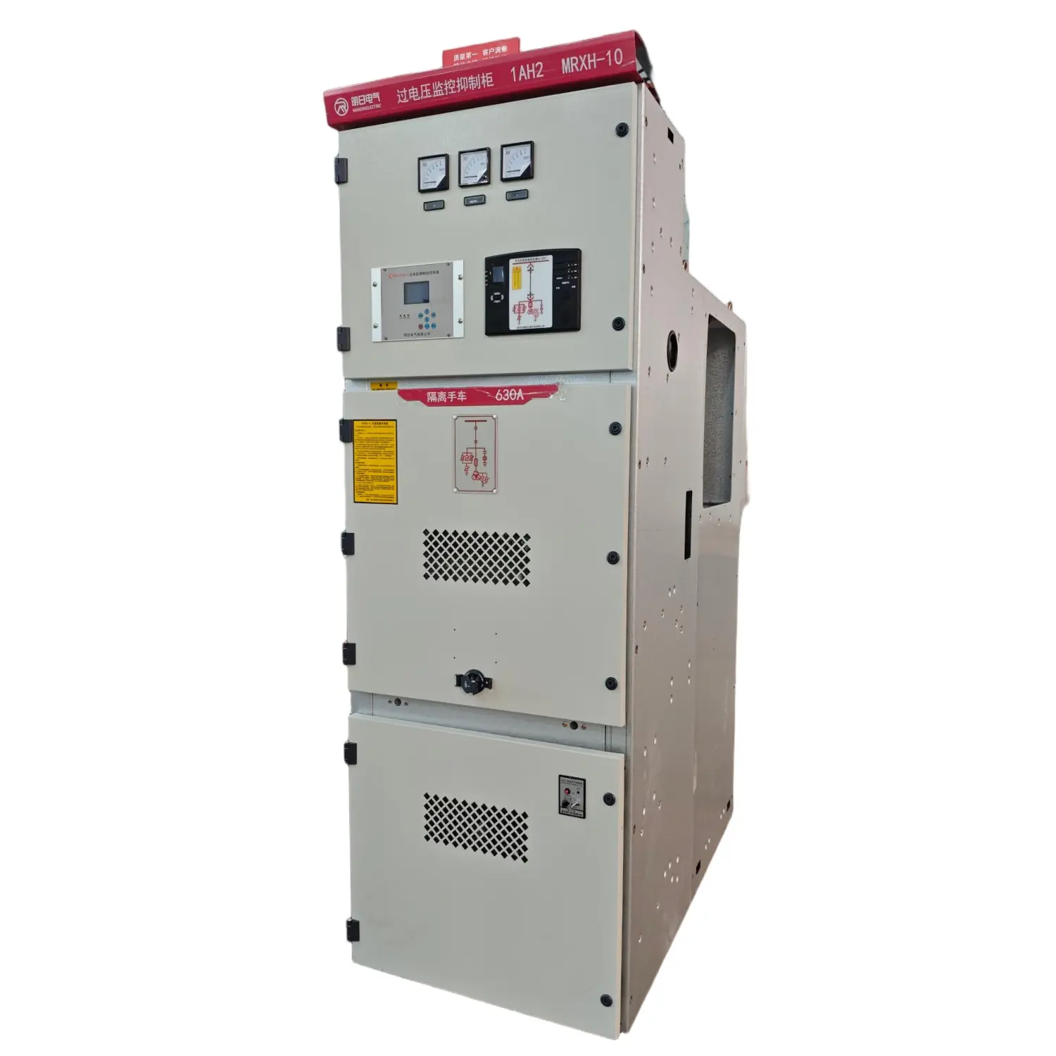

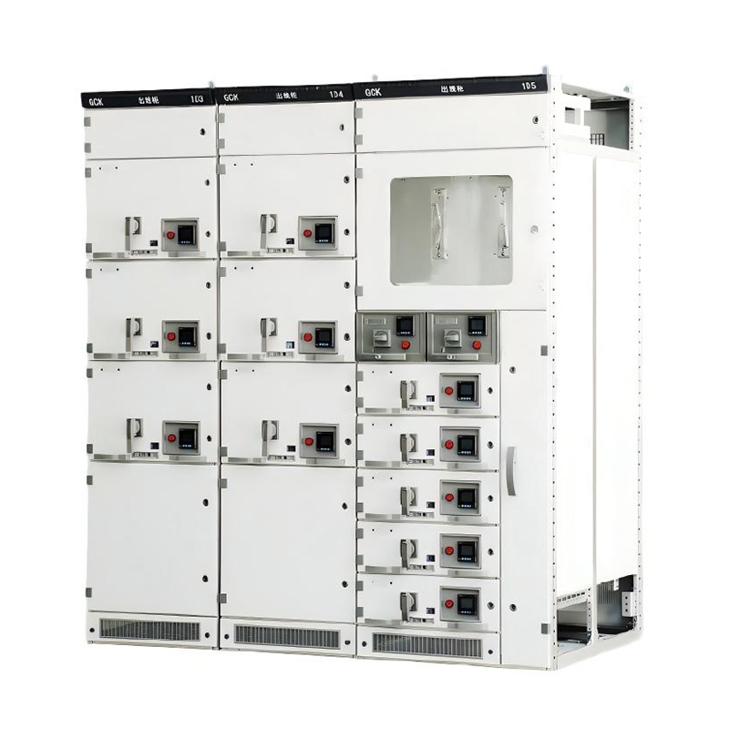
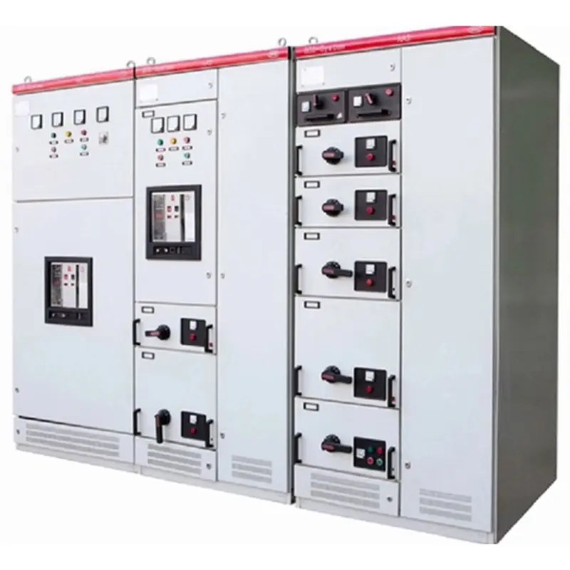
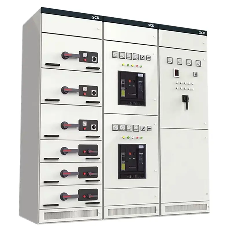
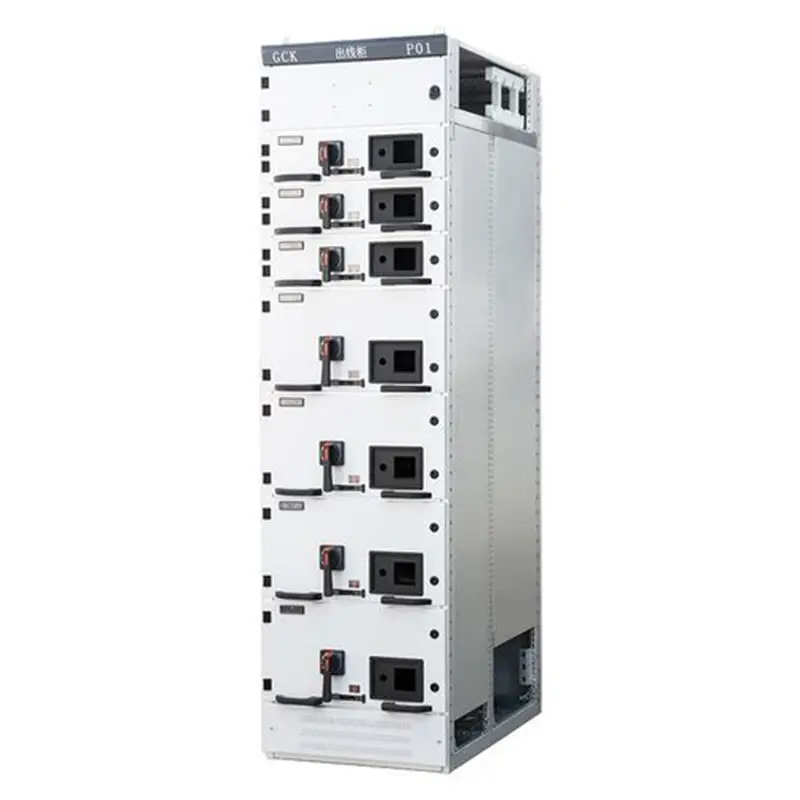
GCK Low voltage withdrawable switchgear for Industrial Plants
Type Designation

| 1 | enclosed |
| 2 | extraction |
| 3 | Usage code: K-Control Center, L-Power |
| 4 | Design Serial Number: 1、2、3 Main Circuit Scheme |
| 5 | Number |
Technical Parameters
| Rated Operating Frequency (Hz) | 50 | |
| Rated Operating Voltage (V) | 380,660 | |
| Rated Insulation Voltage (V) | 660 | |
| Rated Operating Current (A) | Horizontal Busbar | 630-3150 |
| Vertical Busbar | 600 | |
| Rated Short-Time Withstand Current | Horizontal Busbar | 80kA (Valid value) /1s |
| Vertical Busbar | 50kA (Valid value) /1s | |
| Rated Peak Withstand Current | Horizontal Busbar | 176kA/0.1s |
| Vertical Busbar | 110kA/0.1s | |
| Main circuit connector (A) | 200,400 | |
| Auxiliary circuit connector (A) | 10 | |
| Power-Frequency Withstand Voltage (1min) (V) | 2500 | |
| Protection Level | IP40 | |
| Operating Mode | Local, Remote, Auto | |
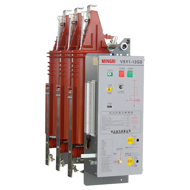
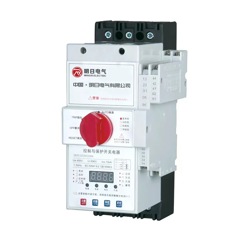
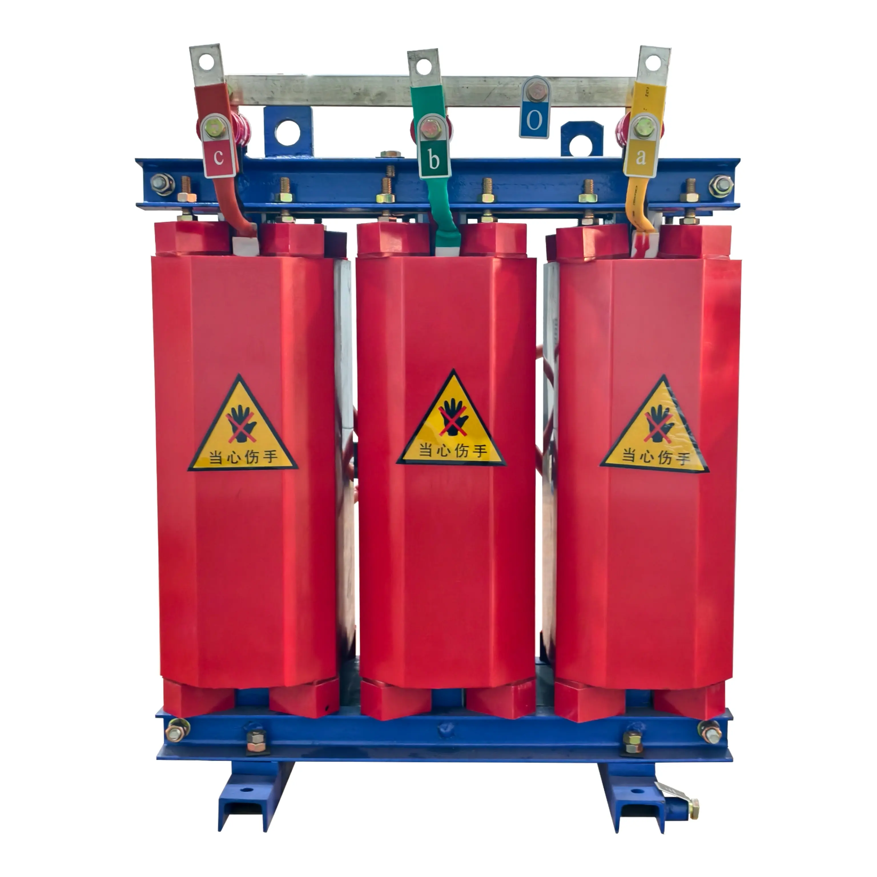
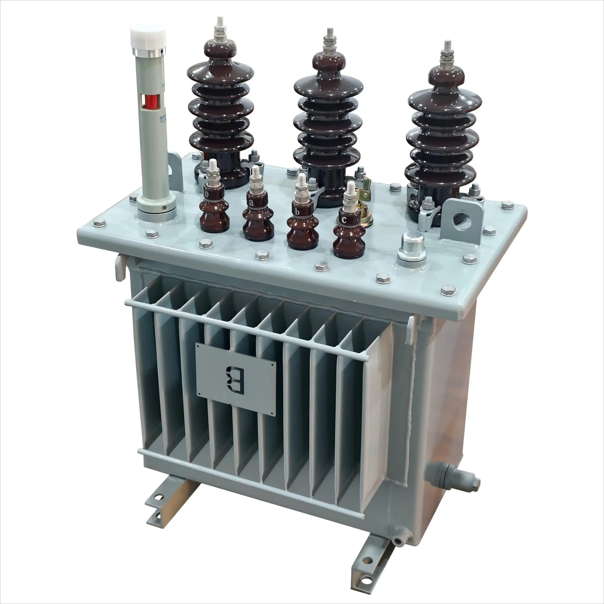
product Display
Outline and Installation Dimensions
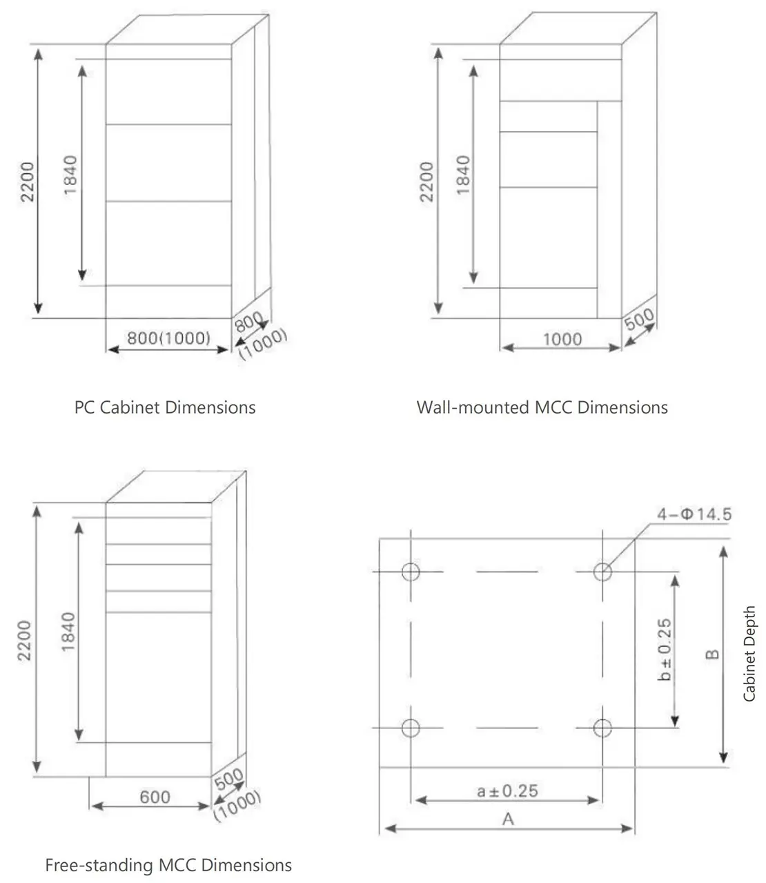
Installation Dimensions & Mounting Holes
| Cabinet Width (A) | Cabinet Depth (B) | Mounting Hole Spacing (a) | Mounting Hole Spacing (b) |
| 800 | 500 | 685 | 385 |
| 600 | 800 | 485 | 685 |
| 600 | 1000 | 485 | 885 |
| 800 | 800 | 685 | 685 |
| 800 | 1000 | 685 | 885 |
| 1000 | 800 | 885 | 685 |
| 1000 | 1000 | 885 | 885 |
Product Installation Foundation Schematic
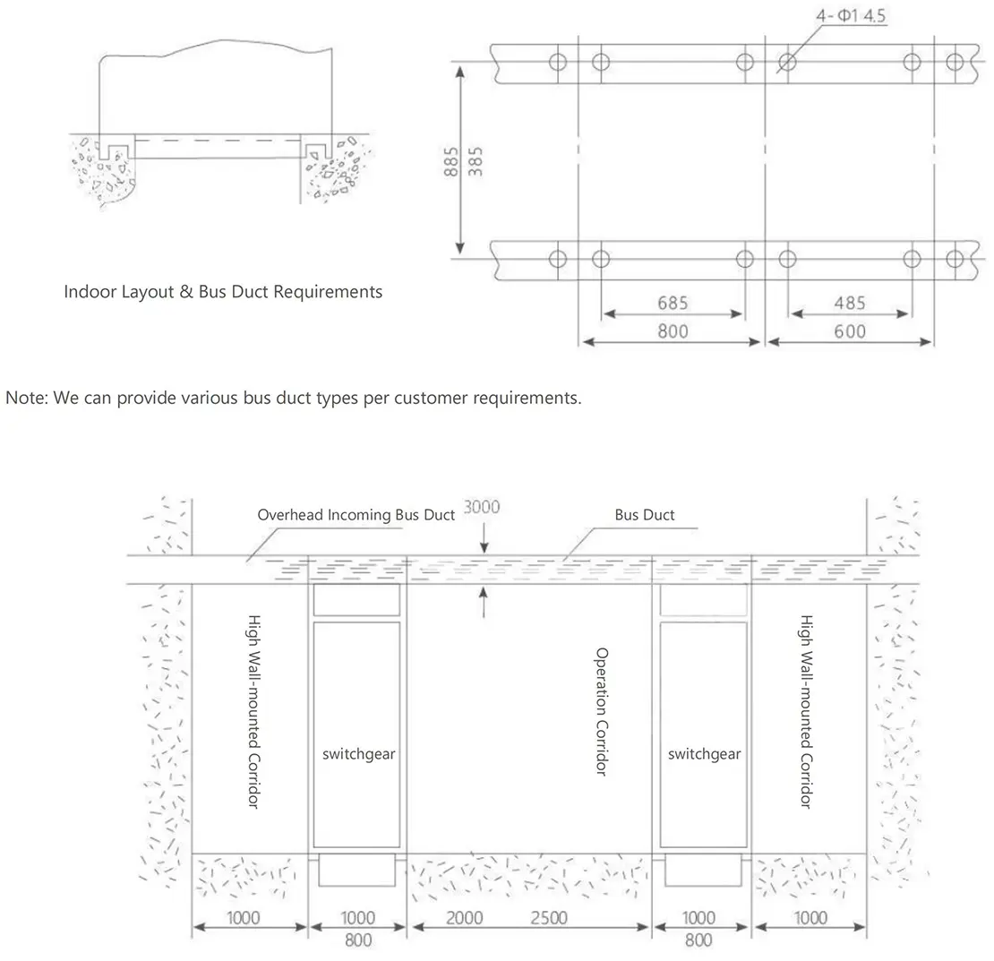
Note: We can provide various bus duct types per customer requirements.
Transportation and Storage Specifications
1. Transportation: Use transport angle plates with ≤120° wire rope angles; avoid direct contact with chassis when using tools.
2. Handling: Prevent tilting/vibration; for minor moves, only pry at test frame corners.
3. Components: No unauthorized disassembly of electrical parts; maintain rain/moisture protection.
4. Documentation: Includes packing list, certifications, manuals, drawings, keys, and matched spare parts.
Ordering Notice
Product operating site and special requirements:
1. Provide product ordering drawings, which should include wiring diagrams and indicate transformer capacity, main component model specifications, distribution branch circuits, and capacity
2. When it is necessary to configure electric energy metering and reactive power automatic compensation devices, the requirements for the configuration of the metering meter and transformer should be provided, and the capacity of the compensation capacitor should be indicated
3. Specify the requirements for surface treatment of the product