

 Claire
 Mr.Fu
Mr.Fu

 Claire


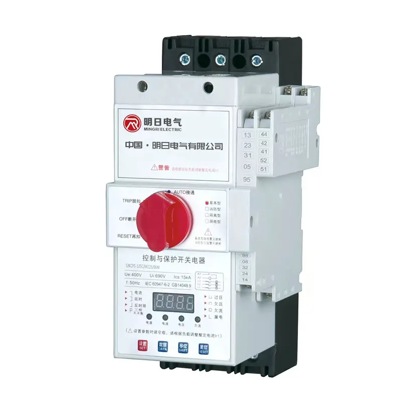
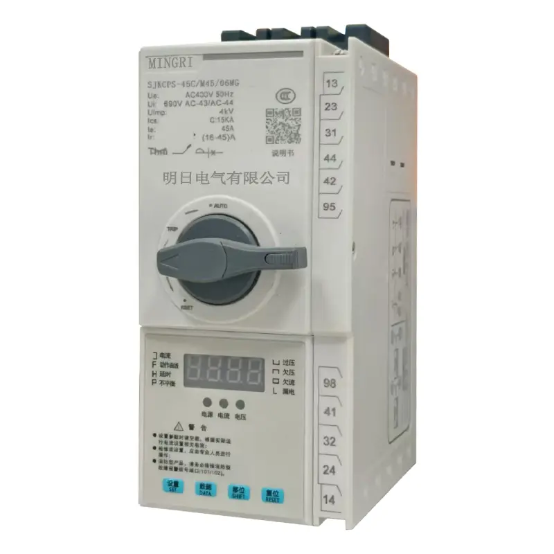
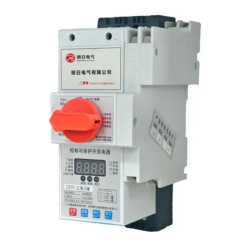
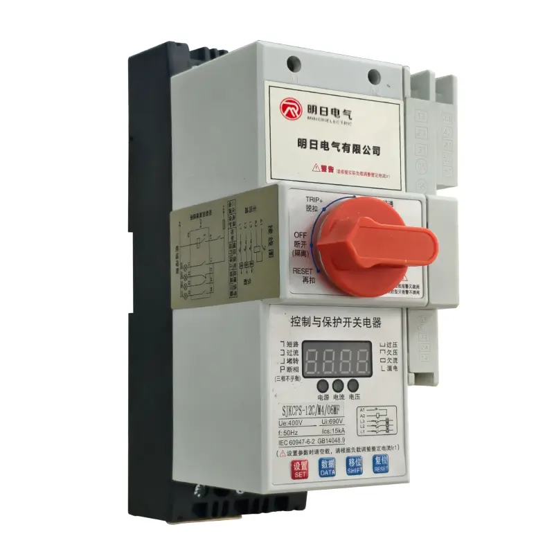
SJKCPS Control and Protective Switching device
Type Designation
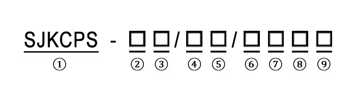
| 1 | Control and Protection Switching Device |
| 2 | Main Frame Current Rating (45,125) |
| 3 | Breaking Capacity Code: C-Economic Type; Y-standard Type; H-High Type |
| 4 | Load Type (Motor M/Power Distribution P) |
| 5 | Rated Current (1A~125A) |
| 6 | Accessories (02,06, 09)(unmarked if not present) |
| 7 | Coil Control Voltage (M:AC230V; Q:AC400V) |
| 8 | Basic Type (unmarked); F-Fire Protection Type (alarm only,no tripping) |
| 9 | G- Isolated Type (unmarked if not present) |
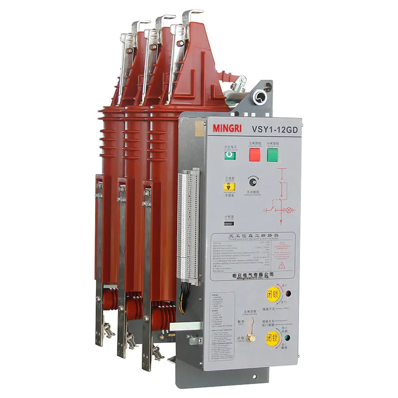
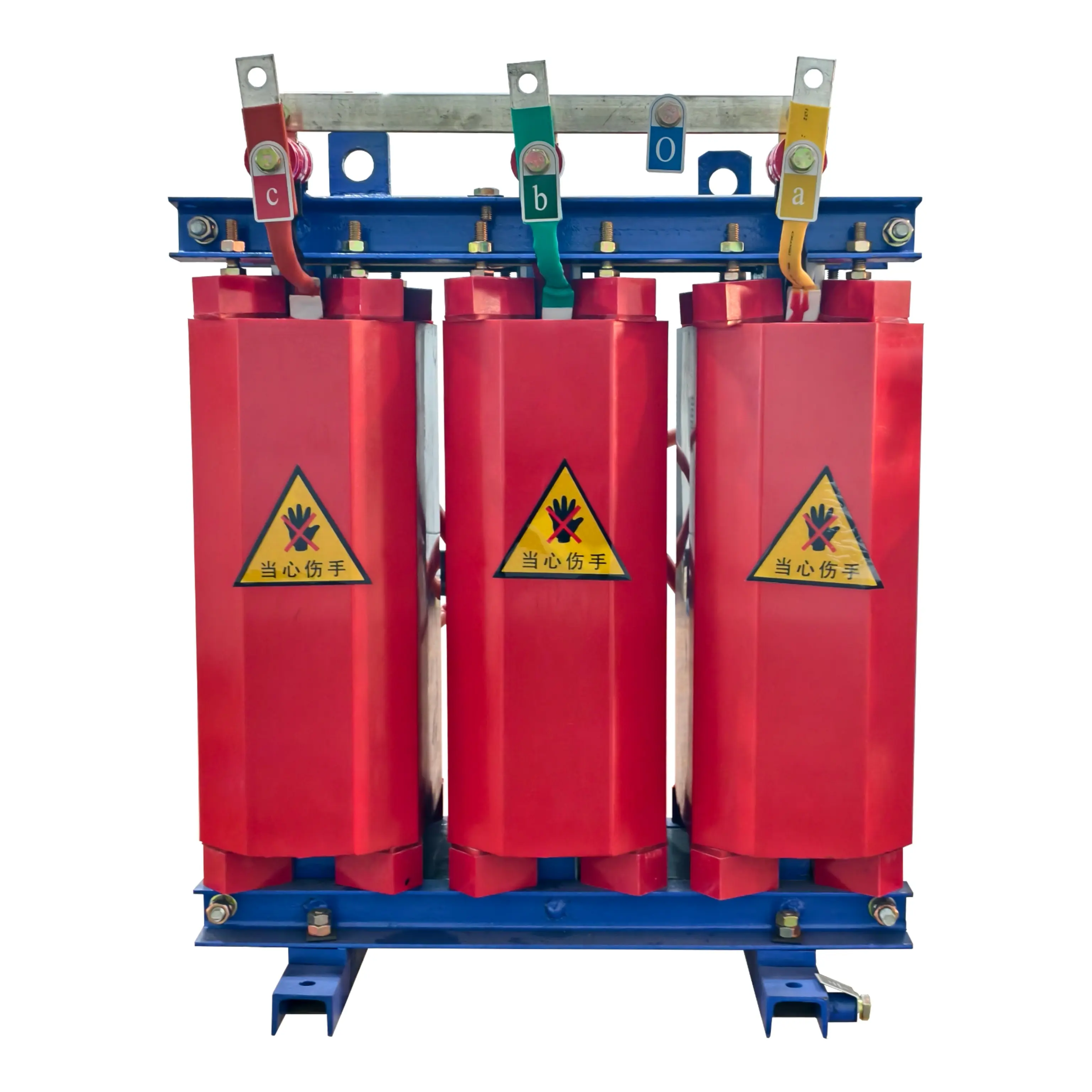
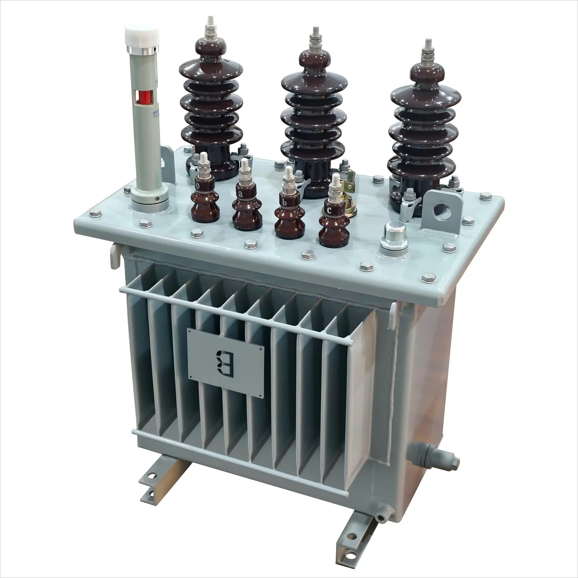
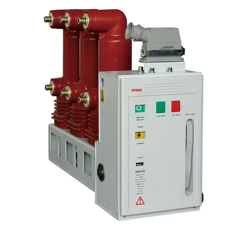
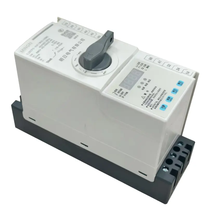
product Display
Technical Parameters
| Frame Current IthA | Main Rated Current InA | Overload Electronic Trip Rated Current Ie (A) | Overload Electronic Trip Current Adjustment Range | 80V Control Power Range (kW) | Utilization Category | Rated Voltage (V) | Rated Frequency (Hz) |
| 45 | SJKCPS-16 | 1 | 0.4~1 | 0.12~0.33 | AC-42 AC-43 AC-44 |
380(400) | 50(60) |
| 3 | 1.2~3 | 0.5~1.5 | |||||
| 6 | 2.4~6 | 1.5~3 | |||||
| 10 | 4~10 | 2.5~5 | |||||
| 16 | 6.4~16 | 4.5~7.5 | |||||
| SJKCPS-32 | 25 | 10~25 | 5.5~11 | ||||
| 32 | 13~32 | 11~15 | |||||
| SJKCPS-45 | 45 | 18~45 | 15~22 | ||||
| 125 | SJKCPS-63 | 63 | 25~63 | 18.5~30 | |||
| SJKCPS-80 | 80 | 32~80 | 30~37 | ||||
| SJKCPS-100 | 100 | 40~100 | 37~45 | ||||
| SJKCPS-125 | 125 | 50~125 | 40~55 | ||||
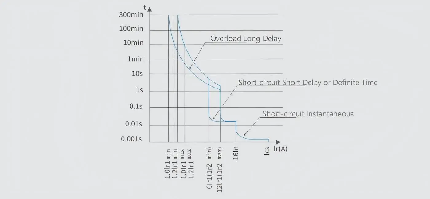
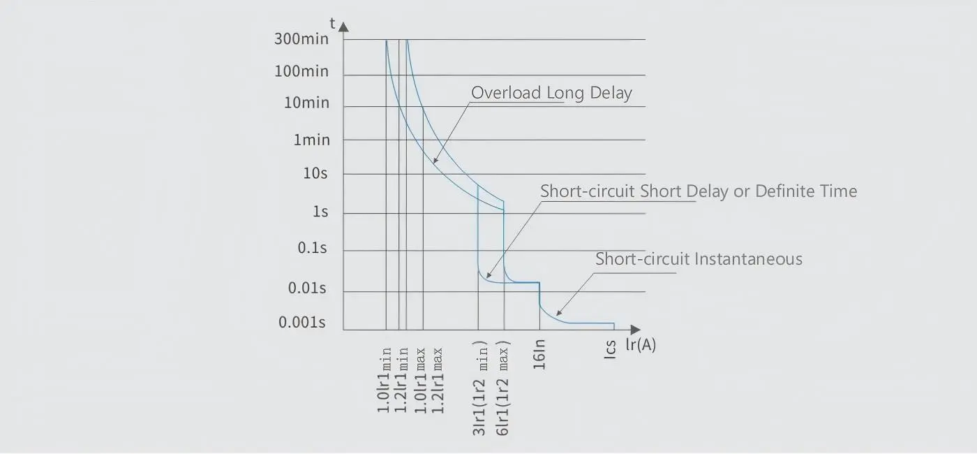
Motor Protection Curve & Power Distribution Protection Curve
◇ Motor Protection Curve
◇ Power Distribution Protection Curve
Product Utilization Categories and Typical Applications
| Circuit | Utilization Category | Typical Applications |
| Main Circuit | AC-20A | Connecting and disconnecting circuits without conditions |
| AC-40 | Power distribution circuits, including mixed resistive and inductive loads with reactors | |
| AC-41 | Non-inductive or slightly inductive loads, resistance furnaces | |
| AC-42 | Slip-ring motors: starting, breaking | |
| AC-43 | Squirrel-cage induction motors: starting, breaking during operation | |
| AC-44 | Squirrel-cage induction motors: starting, plugging/reversing, jogging | |
| AC-45a | Switching discharge lamps | |
| AC-45b | Switching incandescent lamps | |
| Circuit | Utilization Category | Typical Applications |
| Auxiliary Circuit | AC-15 | Controlling AC electromagnetic loads |
| AC-20A | Connecting and disconnecting circuits without conditions | |
| AC-21A | Switching resistive loads, including appropriate overloads | |
| DC-13 | Controlling DC electromagnetic loads | |
| DC-20A | Connecting and disconnecting circuits without conditions | |
| DC-21A | Switching resistive loads, including appropriate overloads | |
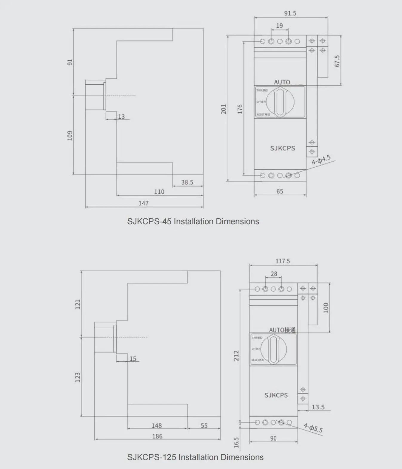
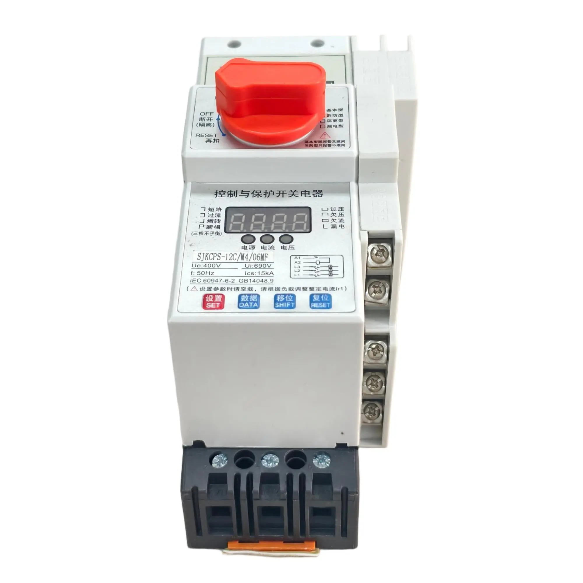
Basic Model Operation Panel Diagram and Installation Dimensions
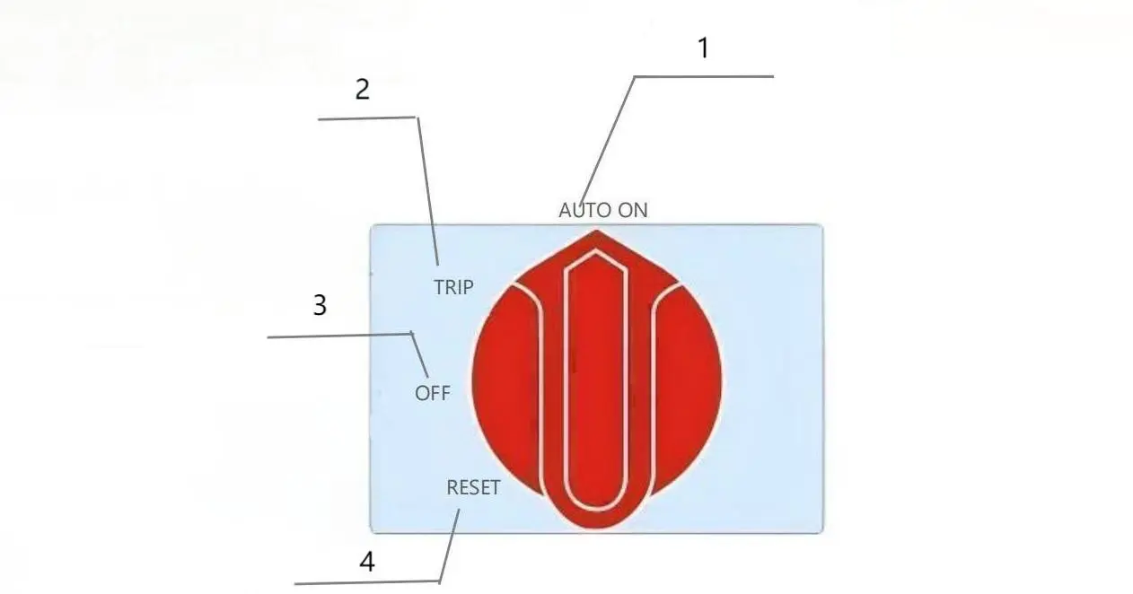
1.Control (Automatic or Manual) Position:
In this state, the internal control coil contact of the SJKCPS switchgear is in the closed position, controlling the circuit connection and disconnection through the coil control circuit. This state allows for remote automatic control.
2.Free Release Position:
The position where both main contacts and electromagnetic coil control contacts are disconnected when corresponding functional modules operate due to faults such as overload, short circuit, phase loss, overunder voltage in a closed circuit.
3.Disconnection Position:
The coil contact is in the disconnected position, and the SJKCPS main contact is also in the disconnected position.
4.Re-engagement Position:
The SJKCPS switchgear can only be freely released when the operating knob is turned to this position, allowing for normal resetting and re-engagement.