What Is a Molded Breaker and How Does It Work?
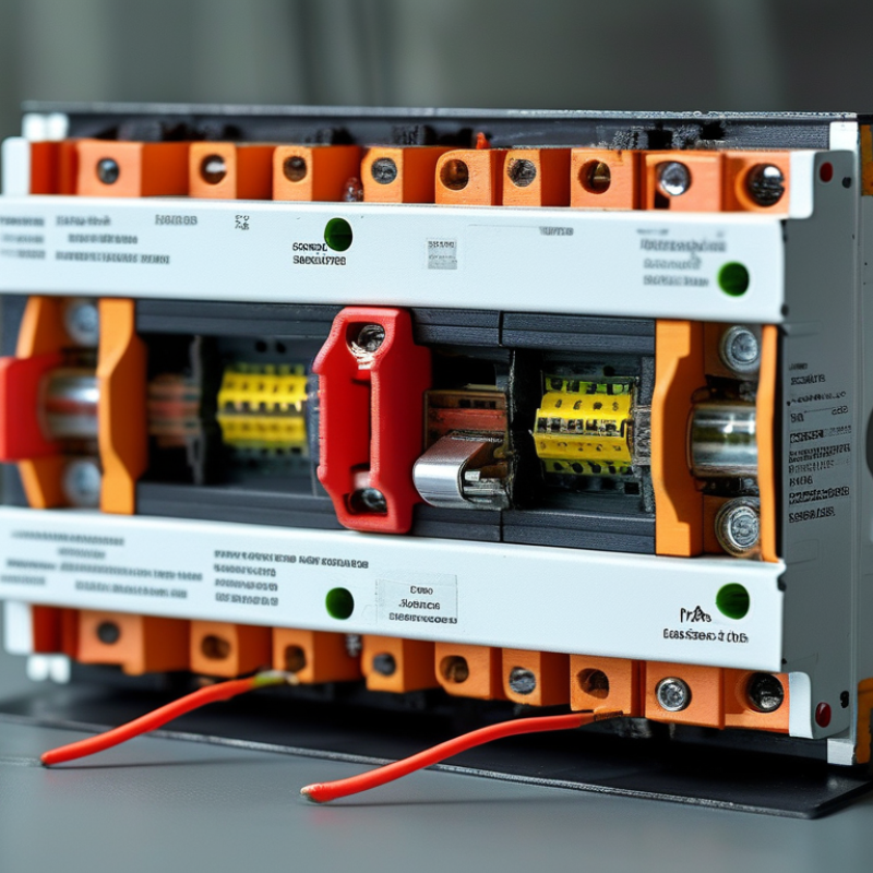
A Molded Breaker protects electrical circuits from overloads and short circuits. Its insulated molded case supports internal conductors, contacts, and trip mechanisms. Inside, current passes through a carefully designed path. Under normal conditions, the contacts remain closed and power flows continuously.
When current rises too high, the breaker reacts. A thermal element responds to sustained overload heat. A magnetic element reacts almost instantly to severe short-circuit current. Some modern units use electronic trip systems for greater accuracy and adjustable protection. The contacts separate, creating a controlled gap that interrupts the circuit. It is a small movement with serious responsibility.
Mike Holt, an electrical educator and code expert, offers a useful warning: “A circuit breaker is a safety device, not a control switch.” That distinction matters in real installations. Repeated manual switching can wear operating parts unnecessarily. A technician should check the breaker’s rated current, interrupting capacity, voltage, connection torque, and enclosure conditions. A mismatched device may appear normal while providing inadequate protection.
The term “molded” describes the protective housing, not a simple plastic cover. The case helps contain heat, mechanical stress, and arcing forces during interruption. However, no breaker works alone. Cable size, installation quality, ambient temperature, and coordination with upstream devices affect performance.
The explanation is not perfect. Breaker behavior varies among designs and manufacturers. Therefore, reliable selection requires the product documentation and qualified technical judgment. Understanding those limitations makes the Molded Breaker easier to specify, inspect, and maintain safely.
Molded-Case Circuit Breaker Definitions in IEC 60947-2 and UL 489
A molded-case circuit breaker is a resettable protective device inside an insulated molded enclosure. The name can mislead. It is not merely a switch. Its contacts carry normal current, while a trip mechanism opens them during overloads or short circuits. Thermal elements respond to sustained overcurrent. Magnetic elements react to high fault current. Electronic trip units can provide more adjustable protection.
IEC 60947-2 defines requirements for circuit breakers used in low-voltage switchgear and controlgear. It addresses construction, performance, temperature rise, dielectric strength, short-circuit testing, and rated service conditions. The standard generally covers equipment up to 1,000 V AC or 1,500 V DC. It also considers rated ultimate and service short-circuit breaking capacities. These ratings should never be treated as interchangeable.
UL 489 focuses on molded-case circuit breakers and circuit-breaker enclosures used for circuit protection in North American applications. Its evaluations include overload operation, endurance, dielectric performance, temperature behavior, and short-circuit interruption. The marked interrupting rating must match the available fault current at the installation point. A common field mistake is choosing a breaker by amperage alone. Voltage, frequency, conductor size, ambient temperature, trip settings, and system fault level also matter. The physical case may look similar across products, but compliance is standard-specific. Verification requires reading the product markings and installation instructions, not relying on appearance. One detail is easy to miss. A breaker can trip correctly yet remain unsuitable for the actual installation.
Thermal-Magnetic and Electronic Trip Units for Overcurrent Protection
What Is a Molded Breaker and How Does It Work?
A molded case circuit breaker protects electrical circuits from damaging overcurrent. Its trip unit detects abnormal current and opens the contacts inside the insulated housing. The housing helps contain heat, sparks, and mechanical stress during interruption. In field work, correct protection depends on the circuit’s load, conductor size, and expected fault current.
Thermal-magnetic trip units use two practical responses. A bimetal element bends when sustained overload heat builds up. This delayed action allows normal starting currents to pass. A magnetic element reacts almost instantly to severe short-circuit current. It releases the mechanism and separates the contacts quickly. Electronic trip units measure current through sensors and process the signal digitally. They can provide more precise long-time, short-time, instantaneous, and ground-fault settings. However, adjustable protection is not automatically safer. Poor settings may cause nuisance trips or leave conductors inadequately protected.
Tips: Match the trip rating with the conductor ampacity and equipment requirements. Check available fault current before selecting interrupting capacity. Test mechanical operation during planned maintenance. For electronic units, inspect control power, connections, and event records. A real installation may not behave like a clean calculation, especially with motor starts or harmonics. Record the final settings, because undocumented changes create avoidable uncertainty. Recognizing that uncertainty is part of responsible electrical work.
A molded-case circuit breaker combines current sensing and a trip mechanism to interrupt excessive current.
Thermal protection responds to sustained overloads, while magnetic protection responds to high short-circuit currents.
The values are shown as multiples of the breaker rated current (In). Thermal values represent IEC conventional reference points;
B, C, and D magnetic bands are IEC 60898-1 reference ranges. Electronic trip units use current sensors and can provide adjustable long-time, short-time, instantaneous, and ground-fault protection.
Short-Circuit Interruption Ratings from 10 kA to 150 kA
What Is a Molded Breaker and How Does It Work?
A molded-case circuit breaker protects conductors inside a rigid, insulated housing. Its trip unit senses overloads and short circuits. Thermal elements respond to sustained heating, while magnetic or electronic elements react within milliseconds to severe faults. The contacts separate, and arc chutes divide and cool the arc. The process is fast, but never perfectly instantaneous.
Short-circuit interruption ratings commonly range from 10 kA to 150 kA. This figure shows the maximum prospective fault current the breaker can interrupt safely at a stated voltage. A 10 kA breaker may suit a distant distribution panel. A 150 kA model may be required near a transformer with high available fault current. The correct value comes from a short-circuit study, not visual judgment. IEEE 1584-2018 also shows that system layout, enclosure size, and electrode position can change arc-flash energy significantly.
IEC 60947-2 and NFPA 70E require engineers to consider tested performance, voltage, installation conditions, and labeling. NFPA 70E:2024 requires arc-flash labels to identify nominal voltage, the arc-flash boundary, and incident-energy or PPE information. NEMA AB 4 guidance emphasizes inspection, testing, and maintenance of molded-case breakers. A high kA number alone does not guarantee protection. Coordination can fail if upstream and downstream trip curves overlap. That assumption needs checking. Calculations should use the actual transformer impedance, conductor length, and utility fault data. Safety margins matter, because field conditions rarely match a clean drawing.
Time-Current Curves, I²t Energy, and Selective Coordination in MCCBs
What Is a Molded Breaker and How Does It Work?
A molded case circuit breaker (MCCB) protects conductors from overloads and short circuits. Its trip unit senses current and opens contacts. The enclosure supports insulation, arc control, and safe operation. Yet protection is not based on one fixed trip time.
Time-current curves show how quickly an MCCB responds at different current levels. A small overload may permit seconds or minutes of heating. A severe fault can trigger almost instantly. The curve is usually a band, not a precise line. Manufacturing tolerance, ambient temperature, and installation conditions affect actual performance. I²t represents current squared multiplied by clearing time. It estimates thermal energy released during a fault. Lower I²t can reduce conductor and equipment stress. However, comparing I²t values without matching voltage and fault conditions can mislead. A common review mistake is treating published curves as field guarantees. They are design references, not promises.
Tips:
Compare upstream and downstream curves on the same scale. Check short-circuit ratings, cable withstand, and trip settings. For selective coordination, keep the downstream breaker operating first whenever practical. Time-current overlap may indicate lost selectivity. Manufacturer test data or an engineered study may be necessary. Do not rely on spacing alone. Real systems are less tidy.







 Claire
 Mr.Fu
Mr.Fu

 Claire